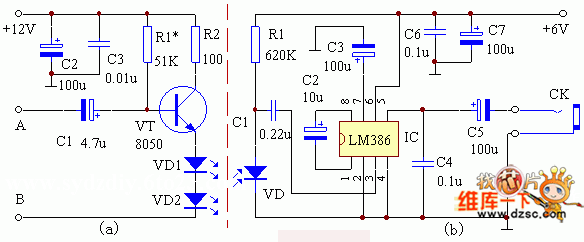
This TV sound infrared transponder has the advantages of simple structure, easy production, no interference, low noise and the like.
working principle

The repeater consists of two parts, transmit and receive. Figure 1 (a) shows the principle of the transmitting part of the circuit. The frequency-adjusted audio (audio) signal is amplified by a triode VT to push the infrared transmitting tube. Since the emission intensity of the transmitting tube is proportional to the current passing through it, the infrared light emitted by VD1 and VD2 is modulated by the audio signal. In order to prevent distortion, VD1 and VD2 should be set to a certain offset. Figure 1 (b) is a schematic diagram of the receiving portion. Its circuit uses an audio amplification integrated circuit LM386. VD is an infrared receiving tube. When the infrared light modulated by the audio signal is irradiated to the VD, an electric signal having the same change rule as the audio signal is generated at both ends thereof, and is coupled to the IC through C1 for amplification. Since the IC has power amplification, it can be used for listening to 1-4 pairs of headphones at the same time.
Component selection and production
Transistor VT selects 8050 medium power tube, PCM = 300mW, ICM=500mA, R2 power is not less than 1/4W, VD is infrared receiving tube (cannot use photodiode, otherwise it will be affected by visible light interference).
The debugging of this transponder is very simple. The transmitting part only needs to adjust R1 so that the quiescent current of VT is around 30mA. As long as the receiving part is installed correctly, it can work without debugging.
The transmitter can be installed inside the TV and powered by a 12V power supply. Signal input terminals A and B are connected to both ends of the volume potentiometer. For the telephone with DC volume control of the integrated circuit, both ends of A and B can be connected to the two ends of the horn, but a switch should be added to turn off the horn (it is more convenient to use the headphone output jack). Adjust the volume so that it travels farthest without distortion.
When two launch tubes are installed, the radiation range should be considered so that their effective radiation angles partially overlap.
The design sensitivity of this transponder is slightly lower, and the purpose is to increase the anti-interference ability. According to the actual measurement, the effective forwarding distance is not less than 3m, which can fully meet the needs of ordinary families.
Universal&Learning Romote Control
Shenzhen Chaoran Technology Corp. , https://www.chaoran-remote.com