This DC high-power low-voltage sodium lamp electronic ballast adopts the inverter plus ballast integration mode, with an overall efficiency of >95%, a working DC voltage of 12V and 24V, and can ignite a low-voltage sodium lamp of 35W to 150W. If solar cells are used in conjunction with wind power.
The maximum lit 250W sodium lamp. This product adopts modular production, internal use of single-chip system control. The introduction is as follows.
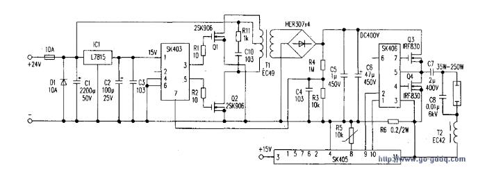
1. Inverter part (see the figure below): The core of this circuit is the module SK403 with square wave oscillation circuit, pre-amplification circuit and PWM voltage regulator circuit. The 24V DC voltage is supplied to the module SK403 and SK405 via the 15V voltage stabilized by ICl (L7815).
The SK403 module's pin function is (1) pin +15V, (2) pin empty, (3), (5) foot square wave oscillation output, (4), (6) pin ground, (7) pin PWM stabilization Press input. (3) and (5) Foot square wave oscillation output signal, to promote the work of two power tubes Ql, Q2, in order to improve the inverter efficiency. The inverter oscillation frequency should be greater than 40kHz, and the rectified voltage of the secondary output of the high-frequency transformer T1 is not stable. The resistance is divided by resistors R3 and R4. The resulting sampling voltage is input to the SK403 (7) pin PWM regulator. The internal pulse width is adjusted to stabilize the output DC voltage at DC400V. High-frequency transformer T1 parameters, primary (low-voltage side) with φ1.25mm enameled wire wound 2x40T, center tap. The secondary uses φ0.25mm × 3 three strands and 130T. Magnetic core, skeleton EC49 horizontal type, impregnated varnish vacuum vacuum paint process to enhance insulation performance. The switching transistors Q1 and Q2 should select Is greater than 30A, and the withstand voltage Vs is a 100V high-power MOS FET. tube. If you choose 2SK564/2SK906 and so on. Adjust the R3 resistance value to set the output level. The function of D1 is to prevent reverse connection of the power supply. It is a protection diode.
2. Electronic ballast part: This circuit is mainly composed of SK405, SK406 two modules. SK405 uses adaptive control technology and adopts two packaging methods: (SMT) SMD and discrete components. The internal system is composed of multiple chip systems. Integrated oscillating circuit, constant power drive circuit, acoustic resonance elimination circuit, and abnormal state protection circuit, and has a preheating trigger function. Each time the trigger time is 20 seconds apart, C8 is the trigger capacitor. This kind of triggering method is much better than other applied voltages and trigger coil methods. Some trigger voltages are high, and the hard-to-start metal halide bulbs and xenon bulbs can be easily ignited. (8) The foot is a current sensor. The current detected by R6 is transmitted from the (8) pin to the internal circuit, and the integral operation is performed internally. The voltage of the internal oscillation is controlled by the voltage-controlled oscillator, and the power is controlled by the frequency modulation method to keep the power constant. Adjust the R5 resistance parameter to change the set output power value. And not affected by other components of various factors. About 2% of the stability of high-intensity discharge lamps in high-frequency work easily produce "acoustic resonance" phenomenon.
The discharge arc is unstable and the light is flickering. In order to eliminate the “acoustic resonance†phenomenon that may occur, the SK405 applies frequency modulation technology. That is, low-frequency modulation of 40 kHz with a frequency of 100 Hz makes the high-frequency output constantly change in the range of 25 kHz to 35 kHz, so that the lamp arc cannot generate a resonance point, making the light emission stable. No flicker. Since the lamp has an open circuit or short-circuit failure of the output circuit, it may occur. Therefore, the SK405 sets an abnormal state protection circuit when an abnormal state occurs in the output circuit of the electronic ballast. The line power of the whole machine drops automatically and stops working. The electronic ballast is not damaged due to long-term open circuit or short circuit. This circuit and the constant power drive circuit are actually an integral circuit and control each other.
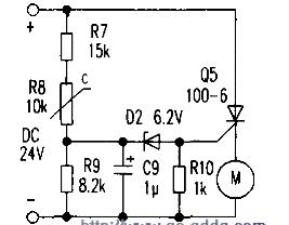
3 over-temperature protection circuit (see right): R8 is a negative temperature thermistor, when the internal temperature of the ballast rises, R8 resistance will gradually decrease. When the temperature rises to about 70°C, the positive terminal voltage of C9 is greater than 6.2V, so that D2 breakdown turns on, thyristor Q5 also turns on, and fan M is powered and the internal temperature of the ballast starts to decrease.
Because transformer T1 is the main heating device of this product. Therefore, when the thermistor R8 is installed, the tape is applied tightly to T1 to ensure the accuracy of the control temperature.
This is a special vozol bar lite electronic cigarette product series. We sell Vozol Vape, Vozol Vape Pen, vozol vape 3000 Puffs, and other vozol vapes.
We are specialized electronic cigarette manufacturers from China, Vapes For Smoking, Vape Pen Kits suppliers/factory, wholesale high-quality
products of Modern E-Cigarette R & D and manufacturing, we have the perfect after-sales service and technical support. Look forward to
your cooperation!
vozol bar lite vape, vozol bar lite vape pen, vozol bar lite 600 puffs vape,vozol bar lite disposable vape kit,vozol bar lite vape kit
Ningbo Autrends International Trade Co.,Ltd. , https://www.supermosvape.com