Using the principle of static pressure measurement: when the liquid level transmitter is put into a certain depth in the measured liquid, the pressure formula on the liquid surface of the sensor is: Ρ = Ï .gH + Po.
where:
P: The pressure on the liquid surface of the transmitter
Ï: density of the liquid to be measured
g : local gravitational acceleration
Po : Atmospheric pressure on the liquid surface
H: the depth of the transmitter into the liquid
At the same time, the pressure of the liquid is introduced into the positive pressure chamber of the sensor through the air-conducting stainless steel, and then the atmospheric pressure Po on the liquid surface is connected to the negative pressure chamber of the sensor to offset the Po on the back of the sensor, so that the pressure measured by the sensor is: Ï. gH , obviously, by measuring the pressure P , the liquid level depth can be obtained.
The working principle of the magnetic flap level gaugeMagnetic flap liquid level gauge: also called magnetic float level gauge, magnetic flip column level gauge. The principle of the connector is developed based on the principle of buoyancy and magnetic coupling. When the liquid level in the measured container rises and falls, the permanent magnet steel in the float is transmitted to the magnetic flip column indicator panel through magnetic coupling, so that the red and white flip column flips 180 °, when the liquid level rises, the flip column turns from white to red, and when the liquid level drops, the flip column turns from red to white, and the junction of red and white on the panel is the actual height of the liquid level in the container, so as to realize the liquid level display.
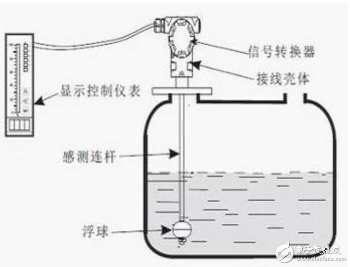
Working principle of float level gaugeThe structure of the float level gauge is mainly designed and produced based on the principles of buoyancy and static magnetic field. The position of the float with a magnet (abbreviated as float) in the measured medium is affected by buoyancy: changes in the liquid level lead to changes in the position of the magnetic float. The magnets and sensors (reed switches) in the floating ball act to change the number of components (such as fixed-value resistors) connected in series to the circuit, thereby changing the electrical quantities of the instrument circuit system. That is, the change of the position of the magnetic float causes the change of the electrical quantity. The liquid level in the container is reflected by detecting the change of the electrical quantity.

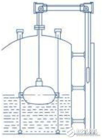
It is designed and manufactured using the principle of mechanical balance. When the liquid level changes, the original mechanical balance will reach a new balance through the movement of the steel belt under the disturbance of the buoyancy of the float. The liquid level detection device (float) drives the steel belt to move according to the liquid level, and the displacement transmission system drives the transmission pin to rotate through the movement of the steel belt, and then acts on the counter to display the liquid level.

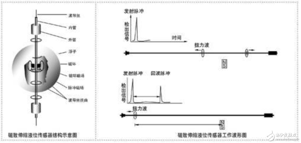
When the sensor of the magnetostrictive liquid level gauge works, the circuit part of the sensor will excite a pulse current on the waveguide wire, and when the current propagates along the waveguide wire, a pulse current magnetic field will be generated around the waveguide wire. There is a float outside the sensor measuring rod of the magnetostrictive liquid level gauge, which can move up and down along the measuring rod with the change of the liquid level. Inside the float there is a set of permanent magnetic rings. When the magnetic field of the pulse current meets the magnetic field of the magnetic ring generated by the float, the magnetic field around the float changes so that the waveguide wire made of magnetostrictive material generates a torsional wave pulse at the position of the float, and this pulse moves along the direction of the float at a fixed speed. The waveguide wire is returned and detected by the detection mechanism. By measuring the time difference between the pulse current and the torsional wave, the position of the float, that is, the position of the liquid surface, can be accurately determined.

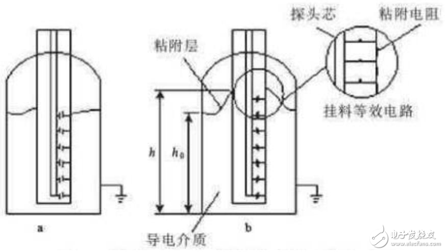
The radio frequency admittance level meter is composed of a sensor and a control instrument. The sensor can be installed on the roof of the warehouse using rod-type, coaxial or cable-type probes. The pulse card in the sensor can convert the material level change into a pulse signal and send it to the control instrument.

Fin Evaporator
Wire tube evaporators are widely used in refrigeration product, such as refrigerators, freezers . wire and tube evaporators need to be well ventilated when installed externally to ensure better cooling efficiency. The smooth flow of refrigerant helps to reduce the load on the compressor, saving energy and extending its service life. The structure is welded with steel wire using powder painting.Evaporator for wire tube are used in commercial freezer and visi-cooler too . We may supply wire tube evaporators according to customers' drawings or samples.
Fin Evaporator,Fridge Evaporator,Freezer Evaporator,Cooler Evaporator
FOSHAN SHUNDE JUNSHENG ELECTRICAL APPLIANCES CO.,LTD. , https://www.junshengcondenser.com