The circuit of Figure 1 is designed for portable-power applicaTIons that require white LEDs with adjustable, logarithmic dimming levels. It drives as many as four white LEDs from a 3.3V source, and adjusts the total LED current from 1mA to 106mA in 64 steps of 1dB each. The driver is a charge pump that mirrors the current ISET (sourced from U3's SET terminal), to produce a current of (215ISET ± 3%) through each LED. Internal circuitry maintains the SET terminal at 0.6V.
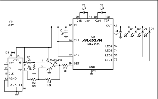
Figure 1. This circuit provides a logarithmic-dimming capability for white LEDs.
To control the LED brightness, op amp U2 monitors the difference between the high-side voltage and the wiper voltage of digital potenTIometer U1. The op amp then mulTIplies that voltage by a gain to set the maximum output current. Zero resistance at the pot's W1 terminal corresponds to minimum LED current, and therefore minimum brightness. Because the SET voltage is fixed (at 0.6V), any voltage change at the left side of R5 changes ISET, and the resulTIng change in LED currents changes their brightness level. R5 sets the maximum LED current:
R5 = 215x0.6 / ILED (Desired)
where ILED is the current through one LED.
U1 is a digital potentiometer with logarithmic taper and an analog-voltage wiper for which each tap corresponds to 1dB of attenuation between H1 and W1 (pins 11 and 9). It contains two pots controlled by a 16-bit code via a 3-wire serial interface. To set the LED current, drive RST-bar high and clock 16 bits into the D terminal of U1, starting with the LSB. Each pulse at CLK enters a bit into the register.
The circuit uses only one pot, so bits 0 through 7 are "don't care" bits. Bits 8 through 14 determine the wiper position: bits 8 through 13 set the code, and bit 14 is "mute." (Logic one at bit 14 produces the lowest-possible output current by setting the left side of R5 at approximately 0.599V.) After entering all 16 bits, enter the code and change the brightness level by driving RST-bar high. Figure 2 shows the logarithmic relationship between an LED current and the pot's input code.
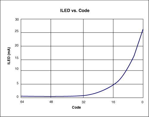
Figure 2. LED current vs. input code for the Figure 1 circuit.
This design idea appeared in the June 10, 2004 issue of EDN magazine.
High efficient charging speed for Toshiba laptop, stable current outlet can offer power for the laptop at the same time charge the laptop battery. The best choice for your replacement adapter. We can meet your specific requirement of the products, like label design. The plug type is US/UK/AU/EU. The material of this product is PC+ABS. All condition of our product is 100% brand new.
Our products built with input/output overvoltage protection, input/output overcurrent protection, over temperature protection, over power protection and short circuit protection. You can send more details of this product, so that we can offer best service to you!
Toshiba Adapter,Adapter For Toshiba,Power Supply For Toshiba,Laptop Charger For Toshiba
Shenzhen Waweis Technology Co., Ltd. , https://www.laptopsasdapter.com