For today's wireless communications industry, CAD/EDA tools are an integral part of the wireless product design cycle. These tools actually reflect the design engineer's focus on the design and time to market. CAD/EDA tools can only achieve the best efficiency for design engineers if they are accurately simulated and easy to use.
This article discusses the design of a 2.6GHz microstrip hairpin bandpass filter that is implemented using the Harmonica circuit-level simulator from Ansoft's Serenade design environment. The design results were exported to Ansoft's Ensemble (2.5-dimensional planar electromagnetic simulator) and LPKF sample plate creation application via Serenade's wiring tool S2A. The main purpose of this design example is to compare Serenade's simulation results with Ensemble's simulation results and measured data.
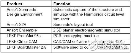
Table 1 summarizes all the CAD/EDA tools used in this design example. Note that all tools are used on the PC.

Table 1. CAD/EDA tools used in filter design.
Filter design
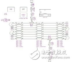
We used a four-chip microstrip hairpin filter structure to implement a general-purpose filter with a response center value of 2.6 GHz and a bandwidth of 3 dB (approximately 280 MHz). The original design passed the principle grabber input of the Serenade desktop (see Figure 1), which used Harmonica's microstrip distribution component library.
The Harmonica distribution model includes a multi-coupling line component (MCPL) model that can be used to design the coupling portion of the hairpin filter. The MCPL uses a full-wave frequency domain algorithm that accurately calculates the electrical characteristics of any line width, spacing, and combination of up to 20 coupled lines at any given frequency range. In the schematic shown in Figure 1, the MCPL component is the eight coupled lines centered in the figure.

Figure 1. Schematic of the microstrip hairpin filter in Serenade.
The folded portion of the hairpin filter is shown as a sub-circuit ("U" type symbol) which includes a straight transmission line portion and a bent connection portion. Since no shielding area is specified for the filter, all radiation effects should be considered. Both Harmonica and Ensemble simulators do this. The substrate was selected for Rogers TMM-4. Its related specifications are shown in Table 2.

Table 2 Rogers TMM-4 substrate specifications
The size of the filter is optimized to achieve the desired bandpass band. Since the MCPL component can simulate any combination of line width and line spacing, we have retained the symmetry design of the filter by optimizing the parameters.
Utility Pole is a tall structure, usually made of wood, metal, or concrete, that is used to support wires and equipment that deliver electricity to homes and businesses. Electric poles can often be found along the side of the road in residential and commercial areas. Power poles are a vital part of the grid, helping to move electricity from power plants to consumers.
Power Pole,Electric Line Transmission Pole,Electric Fencing Pole,Hot Dip Galvanized Pipe
JIANGSU HONGGUANG STEEL POLE CO., LTD. , https://www1.hgsteelpole.com