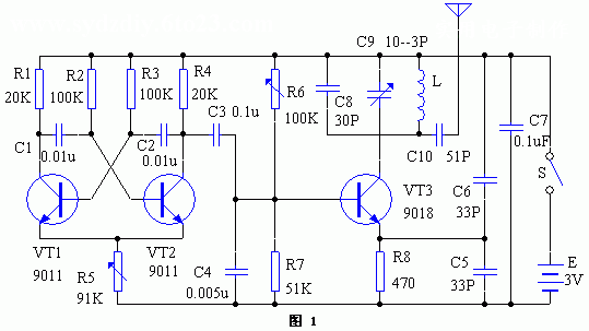
 Working principle The device is a system consisting of a transmitter and a receiver, working in the frequency modulation (FM) band. The circuit operation of the transmitter is shown in Figure 1. It is a multivibrator composed of triodes VT1, VT2 and its peripheral components. Its operating frequency is about 1000Hz. Its signal is taken out through capacitor C3 to modulate the FM oscillator composed of VT3 and its LC components. The modulated FM signal is modulated. Output from C10, radiating into space through the micro antenna inside the machine. The role of C6 is to widen the frequency band and effectively prevent the influence of human body induction on frequency.
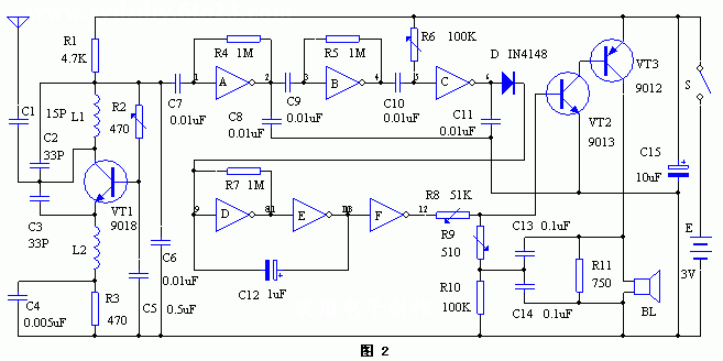
  The circuit operation of the receiver is shown in Figure 2. The triode VT1 (semiconductor triode, also known as "transistor" or "transistor". Two PN junctions can be fabricated on a single crystal of semiconductor germanium or silicon to form a PNP (or NPN) structure. Or N zone) is called the base zone, and the zones on both sides are called the emitter zone and the collector zone. Each of these three sections has an electrode lead, called base B, emitter E and collector C, which can be amplified, oscillated or switched. The isoelectric semiconductor device and its LC component constitute a super regenerative receiving circuit for receiving the FM signal from the transmitter. The gate circuits A, B, and C constitute a signal amplifying circuit, which amplifies, compares, and inverts the received signals to control the 1 Hz oscillating circuit composed of the gate circuits D and E, and then the inverted output of the gate circuit F to control the transistors VT2 and VT3. A complementary audio oscillator consisting of.
 When receiving the transmitter signal, the output of the gate circuit C is positive, the diode VD is turned on, the low frequency oscillator composed of the gates D and E is stopped, the gate F output is low level, the VT2, VT3 complementary oscillator is stopped, and the speaker is stopped. BL does not speak.
Once the signal of the transmitter is not received, that is, the target or child leaves the host 1-15m, the gate circuit C outputs a low level, VD is cut off, the low frequency oscillator composed of the gate circuits D and E operates, and the gate F inverted output frequency is The 1 Hz positive pulse control complementary oscillator circuit sends a short "beep...beep" sound to alert the owner to the attention, until the target can return the control distance to the child, and the alarm sound automatically stops.
Then use the adjusted transmitter to adjust the receiver, disconnect the electromagnetic horn BL in the receiver, connect to the high-impedance earphone, carefully adjust the R2 and the variable capacitor C9 of the transmitter (be careful to avoid the local station). Make the transmitter sound heard in the earphones the loudest and clearest, then gradually pull the distance between the two machines, and then adjust R6 to the required monitoring distance. At this time, the voltage value at the output of the gate circuit C is about 1.5V. After turning off the transmitter, the output of the measuring circuit F should be 3V pulse. Adjusting R7 and C12 can change the pulse width. Turn on the transmitter and the output of the F output is 0V. Turn off the transmitter and connect to the electromagnetic actuator BL. An intermittent “beep...beep†sound should be emitted. If there is no sound or small sound, you should carefully adjust R8, R9, R11 and C13, C14 to maximize the alarm sound. At this time, the measured operating current is about 70 mA. Turn on the transmitter, BL should not sound within the set distance, the waiting current is about 0.5mA.
In order to reduce the volume, the resistors all use 1/16W micro components, the ceramic capacitors and electrolytic capacitors are all reduced, and the BL uses a Φ12mm miniature electromagnetic oscillator. The inductor L1 in the transmitter is wound by a Φ1mm enameled wire on a Φ7.5mm pencil for 3 turns. The inductor L1 in the receiver is identical to L1 in the transmitter. The transmitter and receiver each use two sections of the 5th battery. The quality of the selected components will directly affect the electrical performance of the device. After the welding is completed, the inspection is confirmed to be correct. The power can be turned on for debugging. Use the FM radio to adjust the transmitter so that the radio can receive the signal from the transmitter at the low frequency end. Care should be taken to avoid the local FM radio station, carefully adjust the R5, R6, C9 in the transmitter circuit, and gradually open the receiving distance. The received sound is the largest, and the transmitter operating current is adjusted to a minimum of about 0.3 mA.
The machine works in the ultra-short wave band, and the actual control distance is related to the position, environment and resistance of the two machines. The receiver should not be placed with tin foil cigarettes and other large metal objects, nor can it be held by hand with high frequency parts, otherwise it will get out of control due to frequency drift.
The report on the Global Portable Power Station Market has published by the Market Research Store. The report provides the client the latest trending insights about the Portable Power Station market. You will find in the report include market value and growth rate, size, production consumption and gross margin, pricings, and other influential factors. Along with these you will get detailed information about all the distributors, suppliers and retailers of the Portable Power Station market in the report. The competitive scenario of all the industry players are mentioned in-detail in the report. Due to the pandemic the market players have strategically changed their business plans.
Through the month of the analysis, research analysts predicted that the Portable Power Station market reached million dollars in 2019 and the market demand will reach 8000 million dollars by 2026. During the forecast period 2020 to 2026 the expected CAGR is 70%. The increasing investments in the research and development activities and the rising technological advancements in the Portable Power Station market, increasing the market growth.
Due to the increase of pandemic world-wide several market issues has generated around the world. Such as, economic crisis in various regions along with loss of employment.
Portable Energy Storage System,Portable Energy Storage Market,Portable Power Storage,Portable Energy Storage
Shenzhen Zhifu New Energy Co., Ltd. , https://www.sunbeambattery.com