Last time I shared with you the open Ethernet communication of S7-200 SMART. Although SMART can communicate with third-party equipment through Ethernet, many people always feel that it is troublesome to write bilateral communication programs. Can you achieve unilateral Ethernet? What about communication? In fact, SMART also supports Modbus TCP communication, combining the advantages of TCP communication and Modbus RTU communication, but writing Modbus TCP communication libraries is not a standard function of the software. You need to purchase additional library files developed by Siemens, including up to 8 client libraries. And 8 server libraries.
1. MB_Client instruction library installation
Open STEP 7-Micro/WIN SMART V2.2 and above software, right-click the "Library" node of the project tree, and select "Open Library Folder" from the shortcut menu, as shown in Figure 1-1.
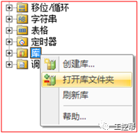
Figure 1-1 Open the library folder
1) Add the MB_Client instruction library to the opened STEP 7-Micro/WINSMART library folder, as shown in Figure 1-2.
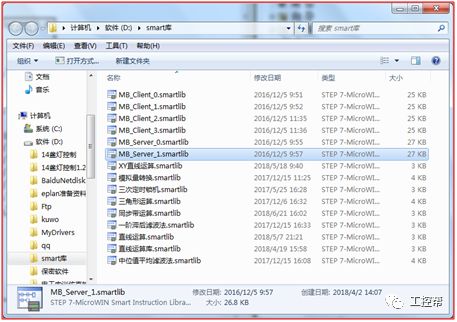
Figure 1-2 Add MB_Client instruction library
Note: The general storage path of the STEP 7-Micro/WIN SMART library folder is C:\Users\Public\Documents\Siemens\STEP7-MicroWIN SMART\Lib, which can be modified by software.
Close the STEP 7-Micro/WIN SMART library folder, then right-click the "Library" node of the project tree, and select "Refresh Library" from the shortcut menu. After refreshing, you can see that the "MB_Client" instruction library has been added to the library node of the project tree, as shown in Figure 1-3. . The method for adding MB_Server server library is similar. .
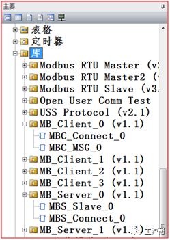
Figure 1-3
2. Communication program writing
With the Modbus TCP communication library, you only need to call the library for programming, which makes the ModbusTCP communication program very simple. First, look at how the client program is written:
1) Establish a connection, as shown in Figure 1-4:
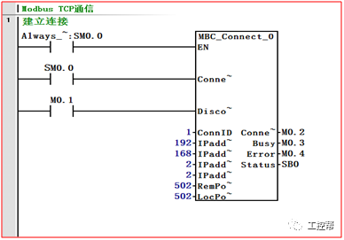
Figure 1-4 Establishing a connection
The parameters of the MBC_Connect instruction are defined as follows:
· EN enable: It must be ensured that every scan cycle is enabled.
· Connect: Start the TCP connection establishment operation.
· Disconnect: Disconnect TCP connection operation.
· ConnID: TCP connection identification.
Note: Modbus TCP belongs to TCP communication, which is also a kind of open user communication, so the ConnID parameter cannot be the same as other TCP, ISO-on-TCP, UDP communication.
· IPaddr1~IPaddr4: Modbus TCP client IP address, IPaddr1 is the most significant byte of the IP address, IPaddr4 is the least significant byte of the IP address.
· RemPort: Modbus TCP client port number.
· LocPort: The port number on the local device.
· ConnectDone: The Modbus TCP connection has been successfully established.
· Busy: When the connection operation is in progress.
· Error: An error occurred when the connection was established or disconnected.
· Status: If the instruction sets the "Error" output, the Status output will display the error code. This error code refers to the instruction error code of the open user communication library. For details, please refer to the STEP 7-Micro/WIN SMART online help
Note: Each MB_Client instruction library can only create one Mdobus TCP connection. If one S7-200SMART needs to connect to multiple Modbus TCP servers, you need to purchase multiple MB_Client instruction libraries with different names (for example, MB_Client_0, MB_Client_1, MB_Client_2, MB_Client_3)
2) Read and write data MBC_MSG, as shown in Figure 1-4:
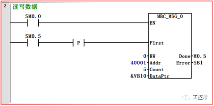
Figure 1-4 Reading and writing data
The parameters of the MBC_MSG instruction are defined as follows:
· EN enable: Only one MB_Client_MSG instruction can be enabled at the same time, and the EN input parameter must be turned on until the Done bit of the MB_Client_MSG instruction is set to 1.
· First read and write request: Each new read and write request needs to be triggered by the signal edge.
· RW read and write request: when it is 0, read request; when it is 1, write request. The switch output coil and save register support read requests and write requests, and the switch input contacts and analog input channels only support read requests.
· Addr reads and writes the Modbus address of the Modbus server: 00001 to 0XXXX are switch output coils; 10001 to 1XXXX are switch input contacts; 30001 to 3XXXX are analog input channels; 40001 to 4XXXX are holding registers.
· Count the number of read and write data: For Modbus addresses 0XXXX, 1XXXX, Count is calculated by the number of bits; for Modbus addresses 3XXXX, 4XXXX, Count is calculated by the number of words; one MB_Client_MSG instruction can read or write up to 120 Words or 1920 bits of data.
· DataPtr data pointer: The parameter DataPtr is an indirect address pointer, which points to the V memory address of the data related to the read/write request in the CPU. For read requests, DataPtr should point to the first CPU storage unit used to store the data read from the Modbus server. For write requests, DataPtr should point to the first CPU storage unit of the data to be sent to the Modbus server.
· Done completion bit: This bit will be automatically set when the read/write function is completed or an error occurs. When multiple MBC_MSG instructions are executed, the completion bit can be used to activate the execution of the next MBC_MSG instruction.
· Error: Error code. The error code is valid only when the Done bit is 1.
As shown in the following table 1-5:
| MB_Client error code | description |
| 0 | No error |
| 1 | TCP send data error |
| 2 | TCP receive data error |
| 3 | Modbus receive response timeout |
| 4 | Request parameter error: One or more input parameters ("Slave" (Slave), "Read and Write" (RW), "Address" (Addr) or "Count" (Count)) are set to illegal values. |
| 5 | TCP connection was not successfully established |
| 6 | Modbus is busy processing another request. |
| 7 | Modbus response error, received response does not match the request. |
| 8 | Modbus response length check error. |
| 101 | The Modbus server does not support the request function of this address. |
| 102 | Modbus server does not support data address: The requested address range of "Addr" plus "Count" exceeds the address range allowed by the server. |
| 103 | Modbus server does not support the data type: the server device does not support the "address" (Addr) type. |
| 104 | Modbus server device failure |
Table 1-5MB_Client error codes
3) Allocate the library memory address for the MB_Client instruction library.
The MB_Client instruction library needs to occupy 300 bytes of V storage area for library memory address allocation. This library memory allocation address cannot overlap with the V memory address pointed to by the MBC_MSG instruction parameter DataPtr, nor can it overlap with the address used by other programs. The library memory address allocation process is shown in Figure 1-5.
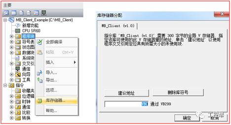
Figure 1-5 shows the MB_Client allocation library storage area
Next is the preparation of the server program:
Note: Each MB_Server instruction library can only create one Mdobus TCP connection. If an S7-200 SMART needs to connect to multiple Modbus TCP clients, you need to purchase multiple MB_Server instruction libraries with different names (for example, MB_Server_0, MB_Server_1, MB_Server_2)
1) Establish a connection with the client, as shown in Figure 1-6:
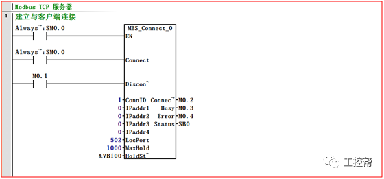
Figure 1-6 Establish a connection with the client
The parameters of the MBS_Connect instruction are defined as follows:
· EN enable: It must be ensured that every scan cycle is enabled.
· Connect: Start the TCP connection establishment operation.
· Disconnect: Disconnect TCP connection operation.
· ConnID: TCP connection identification.
Note: Modbus TCP belongs to TCP communication, which is also a kind of open user communication, so the ConnID parameter cannot be the same as other TCP, ISO-on-TCP, UDP communication.
· IPaddr1~IPaddr4: Modbus TCP client IP address, IPaddr1 is the most significant byte of the IP address, IPaddr4 is the least significant byte of the IP address. If you do not specify the partner IP, you can set it to 0.0.0.0.
· LocPort: Port number on the local device
MaxHold: Used to set the number of word holding registers in the V memory accessible by Modbus address 4xxxx or 4yyyyy.
· HoldStart: Indirect address pointer, pointing to the starting address of the holding register in the V memory of the CPU, that is, which address 40001 starts from.
· ConnectDone: The Modbus TCP connection has been successfully established.
· Busy: When the connection operation is in progress.
· Error: An error occurred when the connection was established or disconnected.
· Status: If the instruction sets the "Error" output, the Status output will display the error code.
The error codes of the MB_Server instruction library are shown in Table 1-7.
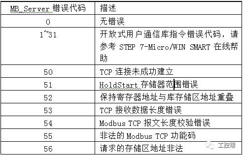
Table 1-7 MB_Server error codes
2) Respond to the command sent by the client, as shown in Figure 1-8.

Figure 1-8 Server response
3) Allocate the library memory address for the MB_Server instruction library.
The MB_Server instruction library needs to occupy 300 bytes of V storage area for library memory address allocation. The memory allocation address of this library cannot overlap with the V memory address pointed to by the MBS_Connect instruction parameter HoadStart, nor can it overlap with the address used by other programs, otherwise it may cause communication failure and communication cannot be realized. The library memory address allocation process is shown in Figure 1-9. .
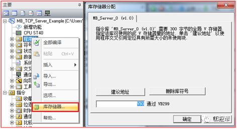
Figure 1-9 Allocating storage for the MB_Server library
Friends who have finished reading this article patiently, congratulations, you have learned the latest Modbus TCP communication function of S7-200SMART, do you want to test it?
Touch Panel For Iphone X,Touch Screen With Oca,Touch Screen Without Ic,Touch Screen Panel With Flex
Shenzhen Xiangying touch photoelectric co., ltd. , https://www.starstp.com