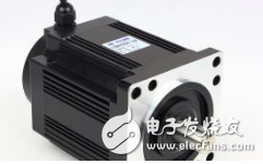
The characteristics of step-and-drag are determined by the characteristics of the drive line, mechanical structure, and stepper motor.
The working state of the stepper motor can be divided into three types: static, steady state and transition state.
First, static:
Static refers to the momentary locked state of the rotor, that is, the DC current (pulse frequency f=0) is passed through the motor control winding, and the rotor is in a state where the lock is unknown. In this state, the motor winding phase current is the largest and the windings are not reloaded, so the motor emits uneven heat in the connected phase (not all). Fever is one of the most serious conditions.
Second, steady state:
The stable synchronization state occurs when the frequency of the control pulse is constant. At this time, the rotor rotates at a constant speed, and it can also be considered as a periodic fluctuation with respect to the synchronous speed. This state can be divided into two categories: the limit (ie, continuous frequency) and the non-limit.
The maximum pulse frequency fmax of the motor output shaft under a certain load and the corresponding maximum speed nmax of the rotor are the limit synchronization state. In this state, the rotor is actually a uniform, non-swaying rotation. This state can only be achieved under certain startup procedures. When the pulse frequency is higher than fmax, the rotor is not synchronized (ie, out of step).
When the control frequency is less than fmax, the motor is in a non-limiting stable state. This state often involves a stable sway (oscillation) of the rotor, which is particularly dangerous in the resonant frequency region.

Third, the basic transition state:
(1) When the frequency is abrupt from zero to start fq, the speed of the motor rotor is accelerated from zero to start at the limit speed (usually the motion limit frequency is referred to as the no-load maximum emotional frequency). Above this maximum abrupt frequency fq (commonly referred to as the start frequency or sensitivity frequency) it is not possible to start the motor without step-out.
(2) When the control pulse is suddenly interrupted, the motor decelerates from the stable synchronous state to the parking lock. The frequency of this stable synchronous state is called the stable limit braking frequency fs. Above this frequency, it is impossible to carry out a non-sliding brake. Only step-down frequency reduction and braking can guarantee no overshoot.
(3) The motor is reversed. When the alternating sequence of winding changes is suddenly changed, the rotor is abruptly changed from a stable synchronous turntable in one rotational direction to another stable synchronous state on the opposite side. There is also a limit inversion frequency ft. Above this frequency, the rotor is out of step, ie there is an error with the given program information.
Start, brake and reversal can be achieved under a variety of (non-zero) initial conditions (angle θ and speed η).
However, the initial conditions strongly influence the specific values ​​of fq, fs and ft, and the drag calculation is thus difficult. Therefore, the initial conditions should be considered when studying the motor frequency characteristics, and the initial conditions of the hard opening rate in the design procedure. Similarly, when selecting a motor, you should also have a detailed understanding of the experimental conditions for these frequency characteristics, as well as the data acquisition (including initial conditions).
Ningbo Autrends International Trade Co.,Ltd. , https://www.mosvapor.com