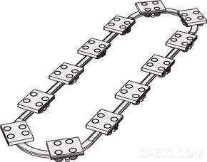
1. Product features The ring rail is a roller-type rail, which is the basis and core component of the circular motion system of the ring rail. General circulating pipelines, such as belt-type pipelines,
The drum-type assembly line has a large movement gap, and does not have sufficient rigidity and positioning accuracy. The cyclic motion system composed of ring guide rails has high rigidity,
The outstanding features of high positioning accuracy, good anti-pollution ability, and higher operating speed can well meet the precision automation requirements of modern factories. The cross section of the sliding block and the guide rail is as follows:

â—Faster linear speed, higher acceleration: The V-shaped roller rolling on the roller V-shaped guide surface can reach a very high linear speed, up to 10m/s; acceleration up to 2G.
â—Lower noise: The V-shaped groove of the roller bearing and the V-shaped surface of the roller V-shaped guide have good contour consistency; the smooth rolling of the V-shaped roller on the roller V-shaped guide surface is compared with the ball guide. Can greatly reduce the noise during high-speed operation.
â—Suitable for use in harsh environments ranging from dust-free to dust: the rolling elements of the bearing in the roller do not directly contact the guide rail surface, and the bearing has good sealing performance; the V-shaped roller moves through the "scratch" movement to remove dust and chips Other impurities are scraped off the surface of the V-shaped guideway to keep the surface of the V-shaped guideway clean, which is very suitable for use in harsh environments. However, if the ball guide is operated in an environment with impurities such as dust and chips, its service life will be greatly shortened.
â—Reduce the accuracy requirements of the installation datum: A V-shaped roller is equivalent to a sliding block of the ball guide. The contact between the V-shaped roller and the V-shaped guide surface is similar to single-point contact; this greatly reduces the installation datum surface Accuracy requirements, time-saving and labor-saving assembly.
â—Lower maintenance and replacement cost: V-shaped guide roller guide rail system, which can replace worn guide rails or rollers individually, without all replacement; by adjusting the eccentric rollers, it is convenient to adjust and obtain the required pre-tightening force.
â—Pre-tightening can be adjusted at any time: When the roller guide rail is assembled, the concentric roller and the eccentric roller are used together, and the pre-tightening force between the roller and the guide rail can be adjusted at any time to ensure smooth operation.
â—Longer service life: In a good working environment, the life of the roller reaches more than 4000KM, coupled with the feature of easy replacement of the roller, the roller guide has a long service life.
2. Typical track layout form linear guide rail and arc guide rail through different combinations of changes, can achieve almost infinite track layout forms. Typical track layout forms in production applications are:
Oval layout, rectangular layout, triangular layout, irregular shape layout. Among them, the oval layout and the rectangular layout are the most commonly used.
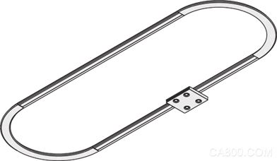
(1) Oval track layout.
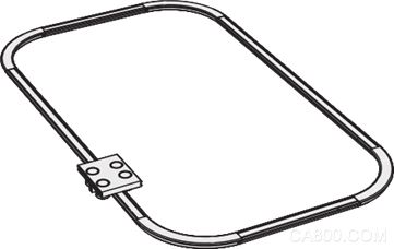
(2) Rectangular track layout.
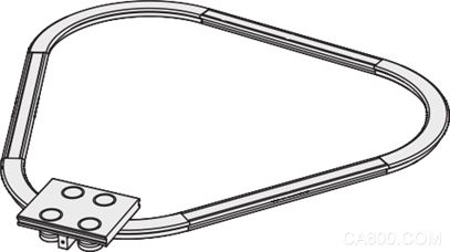
(3) Triangular track layout.
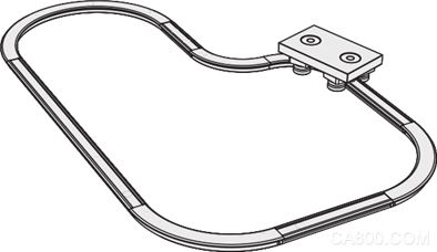
3. Typical driving forms of ring guides are mainly rectangular and elliptical. The driving system mainly includes timing belt type, chain type, screw type, cross arm type and groove wheel type.
(1) Synchronous belt drive Synchronous belt drive is the most commonly used, easy to design, and cost-effective drive method. The servo motor drives the synchronous wheel to rotate, and the synchronous belt and the sliding seat are connected by a slotted or clamped design.
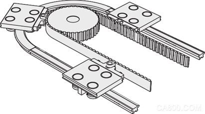
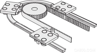
(3) Screw-type drive. The ring guide of this drive mode is characterized by higher moving speed, higher positioning accuracy, and rapid positioning.
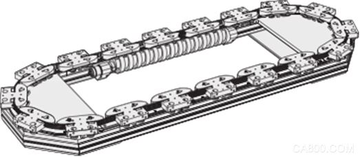
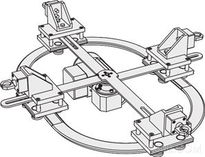
(4) The cross arm drive motor is placed in the center of the system, and the cross arm has a long slot to adapt to the change of the distance between the slider and the motor drive shaft. The transmission mechanism of this drive type is simple, and the distance between different sliders is not easy to change, but the starting force of the motor is large.
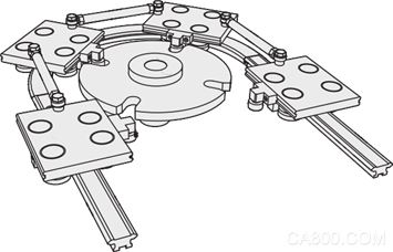
(5) The grooved wheel drives the adjacent sliding blocks to connect with connecting rods, so that the distance between the sliding blocks is not easy to change, and the position is more precise. A driven roller is installed on the sliding block, and the roller engages with the opening on the groove driving wheel. This driving mode requires that the connecting rod between the sliders has a certain degree of flexibility, and the position of the groove wheel and the driven roller meshing with the driven roller needs to leave enough clearance.
4. Example of design and selection The following takes an elliptical orbital motion system driven by a synchronous belt as an example to illustrate the key points of the ring guide design.
(1) Initial selection Generally speaking, the 25-size slider should be used for the heaviest motion load of 10KG, and the 44-size slider should be used for the heaviest motion load of 20KG.
(2) Clarify the requirements and working conditions to determine the conditional parameters in actual production: load on the slider, number of stations (number of sliders), distance between stations (distance between sliders), moving time (or speed) of adjacent stations .

(3) Choose an arc guide with a suitable radius. If the distance between two adjacent sliders is too small, more than one slider will stay on the arc guide section at the same time, which will not be conducive to positioning the slider. Therefore, for There is a recommended minimum distance between sliders for different sizes of arc guides, see the table below:

Determine the center hole diameter D of the arc guide rail according to the actual required station spacing S and compare the recommended minimum sliding block spacing value Smin.
(4) Each parameter of the selection and calculation system corresponds to each type of arc guide rail. Yiheda recommends the use of the following active synchronizing wheel (tooth type AT10) with the following number of teeth. The corresponding relationship refers to the following table:

After confirming the size of the synchronous wheel, the following values ​​can be calculated: The calculation formula for the circumference of the synchronous belt A is: A = N × S
The straight track length L (equal to the center distance of the synchronous wheel) should satisfy the following equation: A = 2 × L + 3.14 × D
(5) Connection method of synchronous belt and slider
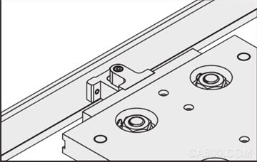
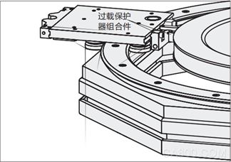
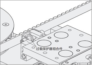
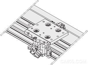
(a) A slotted connecting fastener is installed on the slotted connecting timing belt, and the metal pin installed on the sliding seat engages with the slotted fastener. The connecting fastener must be designed with a long groove, which is to adapt to the slight deviation of the bearing carriage from linear motion to curved motion. (Schematic)
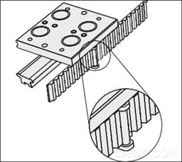
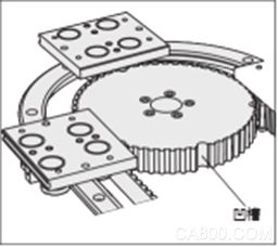
(b) This way of clamping connection does not require screws to pass through the timing belt. Grooves must be machined on the synchronization wheel to avoid interference with clamping parts.
(7) Lubrication system.
In order to avoid excessive friction, a lubricator can be installed to coat the working surface of the guideway with a uniform oil film. The felt in the lubricator is soaked with lubricating oil to wipe the working surface of the guide rail. The inside of the felt is equipped with a small spring to make it have a slight elastic force to ensure sufficient lubrication. Good lubrication conditions can significantly increase the load capacity and life of the system. The lubricator has an oil injection hole, it is recommended to replenish the lubricating oil once a month (recommended No.32 lubricating oil) Unless it is in a special environment such as dust-free or vacuum, it is recommended to install a lubricator in other environments to increase the life of the system.
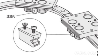
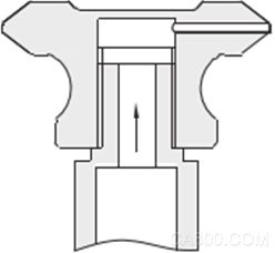
It is also possible to machine oil injection holes on the track to configure an automatic oil injection system to realize automatic replenishment of lubricating oil. Yiheda can provide the automatic lubricator required by the system according to customer requirements.
Link: https://pan.baidu.com/s/19mbBnGSipul33AZaUvmoHw Password: 5ce7
Silicon Transistor are solid-state semiconductor devices with functions such as detection, rectification, amplification, switching, voltage regulation, and signal modulation. The transistor acts as a variable current switch and can control the output current based on the input voltage. Unlike ordinary mechanical switches (such as Relay and switch), transistors use electrical signals to control their opening and closing, and the switching speed can be very fast. The switching speed in the lab can reach more than 100GHz.
Silicon Transistor, Power Transistor, IGBT Transistor, N-Channel Transistor, PNP Transistor
YANGZHOU POSITIONING TECH CO., LTD. , https://www.cndingweitech.com