I. Introduction
The light control circuit plays a vital role in urban street lighting or corridor lighting. The light control circuit can automatically turn on and off the light according to the intensity of the light, so that no one can automatically control, which can reduce the labor intensity of workers. Effective energy conservation. However, the light control circuit has its drawbacks. When there is no light at night, the light will always work, which will result in waste of resources and shorten the life of the light.
At this time, if a sound control circuit is added on the basis of the light control circuit, the illumination circuit is only controlled by the sound when there is no light, and the illumination circuit automatically works when there is footstep or other strong sound. When the sound disappears, the illumination light is automatically turned off. This requires adding a delay circuit under the condition that the light control circuit and the sound control circuit work together to make the illumination light turn off automatically after a certain time delay.
The sound and light control illumination lamp designed in this paper, when the circuit has a sound signal at night, the illumination lamp (simulated by the LED illumination tube) lights up; after the silence is delayed, it is extinguished after 5 seconds; if the sound interval is less than 5 seconds, the LED is continuously lit. No sound is lit during the day. This small, beautiful, practical and energy-saving, can be fixed at the door of the house with mosquito nails, can also be installed in the corridor, can also be used in the factory building, construction site.
With this kind of lighting circuit, people don't have to groping the switch in the dark, and they don't have to worry about the power of the long lamp and the damage to the light bulb. As long as there is footsteps or other strong sounds at night, the lights will automatically light up and will automatically go out after a certain time delay. It is especially suitable for automatic control of street lighting and short-time lighting in corridors and corridors.
Second, the corridor sound control lamp circuit design
The basic principle of 2.1 corridor sound control lights
The circuit is composed of a voice control circuit, a light control circuit, an amplifying circuit and a monostable delay circuit. The functions of the circuit are analyzed one by one and the circuit structure is determined.
The light control circuit preferentially determines the brightness of the light according to the intensity of the light. The sound signal is received by the electret microphone BM. After inverse amplification, the amplified signal is sent to the 2, 6 pins of the NE555 timer. The circuit can control the voice-controlled delay circuit. When the daytime light is strong, the circuit is in the off state under the action of the light control circuit, and does not respond to any sound signal. When the light is weak at night, the light control circuit The function of the circuit is turned on so that the circuit can respond accordingly according to the external sound signal. The output of the NE555 timer controls the 74HC123 voice-controlled delay circuit. This circuit works mainly when the light is weak. This is mainly controlled by the output of the light control circuit.
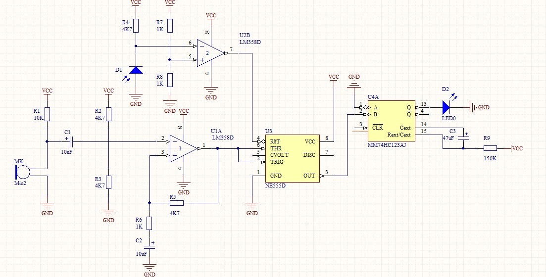
Figure 1 corridor sound control lamp circuit diagram
2.2 Introduction of components
Device list
Table 1 Device List
74HC123 piece | NE555 one | LM358 one | Electret microphone |
Resistance: 330 Ω 2; 1K/4; 4.7K/5; 10K/2; 150K/2 | Potentiometer single circle blue square one 22K Ω | Capacitance: 16V 47uF one; 16V 10uF two; | Photosensitive resistor; one LED ; |
2.2.1 Resistor
There are many types of resistors, which are usually divided into three categories: fixed resistors, variable resistors, and special resistors.
The photoresistor is an original whose resistance value changes with the change of external light intensity (light and dark). The stronger the light resistance, the smaller the light resistance value. Photosensitive resistor, also known as photoresistor, is a resistor made by the photoelectric effect of semiconductor, which changes with the intensity of incident light. It is generally used for light measurement, light control and photoelectric conversion (optical Changes translate into changes in electricity).
Typically, the photoresistor is formed into a sheet structure to absorb more light energy. When it is irradiated with light, an electron-hole pair is excited in the semiconductor wafer (photosensitive layer) to participate in conduction, so that the current in the circuit is enhanced.
2.2.2 electret microphone BM
The electret microphone has the characteristics of small size, simple structure, good electroacoustic performance and low price, and is widely used in cassette recorders, wireless microphones and voice control circuits. It is the most commonly used condenser microphone. Due to the high input and output impedance, a field effect transistor is placed in the microphone housing as an impedance converter. For this purpose, the electret condenser microphone requires a DC operating voltage during operation. Structure and principle The electret microphone consists of two parts: acoustic and electrical conversion and impedance transformation.
The key component of acoustic-electric conversion is the electret diaphragm. It is a very thin plastic film with a pure gold film on one side. Then, after passing through the high-voltage electric field, the opposite sides are respectively charged with opposite charges. The vaporized gold of the diaphragm faces outward and communicates with the metal casing. The other side of the diaphragm is separated from the metal plate by a thin insulating collar. Thus, a capacitor is formed between the vaporized gold film and the metal plate. When the electret diaphragm encounters acoustic vibration, the electric field across the capacitor changes, resulting in an alternating voltage that varies with the change in sound waves. The capacitance between the electret film and the metal plate is relatively small, generally several tens of pF. Therefore, its output impedance value is very high (Xc = 1/2 ~ tfc), about tens of megaohms or more. This high impedance cannot be directly matched to the audio amplifier. Therefore, a junction field effect transistor is connected to the microphone for impedance transformation. The FET is characterized by extremely high input impedance and low noise figure. The common field effect transistor has three poles: the source (S), the gate (G) and the drain (D). Here is a dedicated FET that recombines a diode between the internal source and the gate. The purpose of the diode is to protect the FET when it is subjected to a strong signal. The gate of the FET is connected to the metal plate. Thus, there are three output lines for the electret microphone. That is, the source S, generally with a blue plastic wire, a drain D, generally with a red plastic wire and a braided shield wire connecting the metal casing.

Figure 2 electret microphone
2.3, the working principle of electret microphone
The electret microphone is small in size, simple in structure, good in electroacoustic performance, low in price, and widely used.
When a polymer polarized film is produced, a certain permanent charge (Q) is injected. Since there is no discharge loop, the amount of charge is constant. Under the action of sound waves, the polarized film vibrates with sound, and thus the back pole The distance also changes, that is, the capacitance between the lock polarizing film and the back electrode changes with sound waves.
We know that the formula for the charge on the capacitor is Q = C × V, and V = Q / C is also true. The total charge of the electret is constant. When the plate retreats under the sonic pressure, the capacitance decreases, and the voltage between the two poles of the capacitor increases inversely. On the contrary, the voltage between the two poles of the capacitor increases. Will be inversely proportional to the reduction. Finally, the voltage across the capacitor is taken out by the field effect with very high impedance, and at the same time, the voltage corresponding to the sound can be obtained. Because the FET is active, it requires a certain bias and current to operate in the amplified state. Therefore, the electret microphone must be added with a DC bias to work.
2.4, electret microphone selection note
The price of the electret microphone is very low, and the replacement process is done after the damage. The following points should be noted regarding the electret microphone selection:
(1) There is no direct replacement between the two- and three-pin electret microphones. In general, no circuit replacement is required.
(2) This type of microphone has no model, and the same number of pins can be replaced, but there is a difference in performance.
2.5 555 timer circuit
The integrated timer 555 circuit is a digital and analog hybrid medium-scale integrated circuit, which is widely used. It is a circuit that generates time delays and multiple pulse signals due to internal voltage
The standard uses three 5K resistors, so it is named 555 circuit. The circuit types are bipolar and CMOS, and their structure and working principle are similar. The logic functions and pinouts of the two are identical and easy to interchange.
The 555 circuit forms a one-shot, as shown in Figure 3.
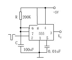
Figure 3 monoflop
The internal circuit of the 555 timer is shown in Figure 4.
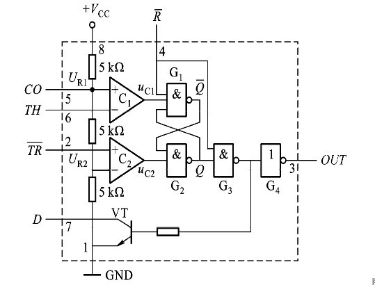
Figure 4 Internal structure of the 555 timer
2.6 74HC123
The 74HC123 is a monostable trigger. Its RxCx (7,15) and Cx terminals (6,14) are connected to the resistor and capacitor, which determines the single pulse width generated by the Q terminal after the trigger. Rbar (3,11) is low-level zero, and is high when not reset. Abar (1,9) is the falling edge trigger input, triggered by a negative pulse with Abar, and held high when not in use. B (2,10) is the rising edge trigger input. It is triggered by positive pulse through B. When not used, it is low... Q (5,13) and Qbar (4,12) output positive and negative timing single pulses respectively.
The action of the one-shot trigger in the device is to restore the pre-trigger state only when the trigger signal is sustained for a certain period of time. The peripheral resistor capacitance determines the one-shot time, because the trigger is triggered by the edge, rising or Falling edge. The difference between the re-triggering monostable is that the monostable after the previous trigger does not restore the pre-trigger state and there is a trigger signal, and the re-triggering monostable will continue to maintain the steady-state given one-shot time at the trigger edge. Monostable is to ignore the trigger signal after flipping. This chip can also be used as a multivibrator.
74HC123 monoflop. It has two inputs, A is active low and B is active high. There are two outputs, just the opposite. Using an external resistor and capacitor as the timing component, the time is set by itself, which is easier to use than the 74LS circuit. The monostable flip-flop 74HC123 and peripheral circuitry implement this function. 74HC123 is a double re-triggerable monostable. The width of the output pulse mainly depends on the timing resistor R and the timing capacitor C. The pulse width is calculated as the product of the capacitance value and the resistance value: WP=R?C, in actual design. Medium R = 5 kW, C = 80 pF, output pulse width is 400 ns, and amplitude is about 5V. The pulse fast edge amplification and emitter follower output circuit, the main function is to accelerate and amplify the shaped and expanded trigger pulses to obtain a pulse signal with a higher amplitude and a faster rising edge to trigger the FET 2SC3306.
2.7 LM358
The LM358 includes two high-gain, independent, internal frequency-compensated dual op amps for a single supply with a wide voltage range, and is also suitable for dual-supply operation. Applications include sense amplifiers, DC gain. The module and all other single-supply operated op amps are used.
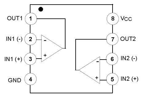
LM358 pin diagram and pin function
The LM358 is available in a plastic 8-lead dual in-line and patch-mount package.
Features of the LM358:
. Internal frequency compensation
Low input bias current
Low input offset voltage and offset current
Common mode input voltage range, including ground
Differential mode input voltage range is wide, equal to the supply voltage range
. DC voltage gain is high (about 100dB)
. Unity gain bandwidth (about 1MHz)
Wide supply voltage range: single supply (3-30V);
. Dual power supply (±1.5 ± 15V)
Low current consumption, suitable for battery power
. Output voltage swing is large (0 to Vcc-1.5V)
Third, hardware circuit installation and debugging
In the process of hardware installation, we encountered a lot of problems. The first time I used the board, I was not familiar with the internal connections, and I made a lot of mistakes.
The first is to install the components and place their positions. The relationship between the two has a good representation on the circuit board, making it easy to see at a glance, and to achieve aesthetics and easy connection of the line, try to use the least number of lines, it does not look messy.
Then what you need to do is analyze the circuit diagram and wire it on the board. The tools used are various pliers, tweezers, etc. Soldering, solder is generally used as solder. It has good fluidity and adhesion. Sufficient mechanical strength under certain temperature, humidity and vibration shocks. Moreover, it has the advantages of corrosion resistance and ease of use.
Flux: The function is to remove oil, prevent the weldment from being thermally oxidized, and enhance the fluidity of the solder.
Commonly used electric soldering irons are three types: external heat type, internal heat type and quick heat type. Generally, the power should not be too large. If the power used is too large, it is difficult to grasp the heat, and it is easy to overheat and damage the components.
The quality of the solder joint is directly related to whether the whole circuit board can work normally, and it is also the basic work that every operator must learn and master.
Welding sequence and method
First measure, make records, clean, hang solder, and finally check and measure.
Welding method:
1. Hold the electric iron on the right. The left hand holds the component or wire with a needle-nose pliers or tweezers. Before soldering, the soldering iron should be fully preheated. Tin on the tip of the tip and a certain amount of solder.
2. Place the tip of the soldering iron close to the solder joint. The soldering iron is at an angle of approximately 60 degrees to the horizontal. In order to facilitate the flow of molten tin from the soldering iron tip to the solder joint. The time that the tip stays at the solder joint is controlled for 2 to 3 seconds.
3. Lift the tip. The left hand still holds the component. The tin at the solder joint is cooled and solidified before the left hand can be released.
4. Turn the lead with tweezers to make sure it is not loose. Then use the nipper to cut off the excess leads.
After the line is connected, debug it. The correct phenomenon is that the power light is turned on and off, the photoresistor is covered, the hand is turned, the light is on, and after a few seconds, the light is off. But in our design process, there was an error: first, there was a short circuit on the line, and the internal connection of the board was not measured, and the ground line was not connected.
Mini PC
Are you tired on big and messy wires on traditional computer tower? If yes, mini pc bring clean and space saving working environment back to you. Whatever daily tasks, like browsing web pages, documents checking or making, online teaching or learning, entertainments, etc. Or heavy duty handling, like photshops, video or music editing, gaming, apps developing, engineering drawing, designing jobs, etc. You can always find a right pc mini intel at this store.
Mini PC Office is an most and popular series designed for those who mainly run WPS, photoshops, PR, email, entertainments, etc. Sometimes, also call it as mini pc officeworks or home assistant mini pc.
Mini Gaming PC comes with higher level processors, like intel i3, i5, i7 10th, 11th or 12th; bigger memory and storage, like 16GB or 32GB ram, 512gb up to 1tb. Of course, rich slots support linking with two or more monitors or devices.
Except mini pc windows 11, there are also All In One PC , Student Laptop, Gaming Laptop , Android Tablet, Yoga Laptop , etc.
Mini PC Windows 11,High Performance Mini PC,Mini PC DDR4,PC Mini Intel
Henan Shuyi Electronics Co., Ltd. , https://www.shuyihost.com