Research on Realizing Serial Communication between MSP430 and Microcomputer Using Capture and Compare Function
1 Introduction:
MSP430 series MCU is a new generation of ultra-low power 16-bit MCU launched by American TI company in 2000. Because of its complete functions, ultra-low power consumption, easy development, and low cost, it has already received the attention and application of the majority of engineering and technical personnel in China. Engineers mainly consider the performance and cost of the model when choosing a model. Therefore, the 11x series, 31x series, and 41x series of MSP430 are favored by many engineers in small instruments and general applications. A common feature of these models is that there is no hardware UART module inside. This brings up a question. How do these microcontrollers implement serial communication? This article studies this problem, analyzes and studies the characteristics of the capture comparison function in MSP430, and the method of using the capture comparison function to achieve serial communication. Taking MSP430F413 as an example, the software code and hardware circuit for serial communication between it and microcomputer are introduced.
1 Introduction of the capture comparison function:
The MSP430 series of single-chip microcomputers have integrated function modules for capturing and comparing. The introduction of the capture comparison function is mainly to improve the ability and speed of the I / O port to process transactions. Capture comparison is not a very new concept. Readers who have used Intel's 16-bit microcontrollers such as 80196MC will find that the capture comparison function in MSP430 is similar to the EPA function in 80196 series microcontrollers. In the following, in conjunction with the need to achieve serial communication, a brief introduction to the relevant concepts of capture comparison.
The capture comparison module is used to capture the time when an application event occurs, or to generate a timed interval. If the corresponding interrupt is allowed, then the completion of a time capture or a timed interval, the capture / compare module will generate an interrupt. Each capture compare module can correspond to a set of hardware pins. Figure 1 is a block diagram of the capture comparison module.
The capture function can capture the change of the state of the selected input pin, it can choose to capture the rising edge, falling edge, front and back edges. If the corresponding change is captured, the timer count value will be copied to the capture compare register CCR, and a corresponding interrupt will be generated. In serial communication, it is the characteristics of the capture function to capture the start bit information.
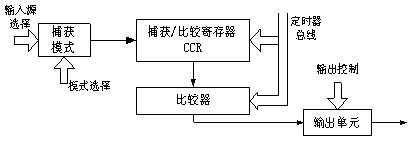
Figure 1: Block diagram of the capture compare module
The comparison function is to continuously compare the set value in the CCR with the count value in the timer by means of a comparator. When the two are equal, an interrupt is generated and the set output is generated. By using the comparison function, accurate time intervals can be obtained. Using this feature, an accurate baud rate generator can be constructed to provide a time reference for serial communication.
2 Methods for serial communication using capture and comparison This section specifically describes how capture and comparison functions work when implementing asynchronous serial communication.
2.1 Receiving process
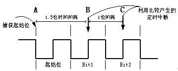
Figure 2: Schematic diagram of timing analysis of capture and comparison functions during serial communication reception
In asynchronous serial communication, each data frame generally consists of 1 start bit, 8 data bits, 1 parity check bit, and 1 stop bit. Figure 2 shows the timing of the first 3 bits of a data frame. When receiving a data frame in this format, the start bit must be determined first for frame synchronization. In MSP430, the capture function is used to capture the lower edge of the start bit (see the appendix program code for details). As shown in Figure 2, the start bit is captured at point A. The system stores the current timer value (T0) into the CCR and generates an interrupt. It is very important to deal with the interruption generated by point A. In this interrupt handler, the capture function is converted to a comparison function, and the 1.5-bit time interval (T1.5) is added to the CCR, that is, CCR = T0 + T1.5. In this way, when the 1.5-bit time interval is reached (point B), the value of the timer is equal to T0 + T1.5. An interrupt will be triggered by this comparison function, thus achieving precise timing of the 1.5-bit time interval. In this interrupt handler, you can read the status of the input pin to receive Bit1 information, and then use the compare function to generate a 1-bit time interval (T1) timing. After that, when the next T1 time arrives, the compare function will trigger another interrupt (point C). Bit2 information can be read in the interrupt service routine at this time. Repeat 8 times in this way to complete the reception of one byte of data.
2.2 The sending process is relatively simple compared to the receiving process. Use the compare function to generate a time sequence with a 1-bit interval (T1), which is equivalent to a baud rate generator. One bit of data is sent in the interrupt service routine triggered by the compare function each time, and so is executed cyclically, so that one data frame can be sent. A data frame of asynchronous serial communication is often 10-bit or 11-bit. For this, you can take advantage of the MSP430's 16-bit machine feature, arrange all the bits of the data frame in a word to be sent, and then shift to send, without special programming to generate the start bit and stop bit. (See the program code and description in the appendix for details)
2.3 The determination of the baud rate and the arrangement of the interruption As can be seen from the above analysis, the baud rate of the serial communication is mainly related to the 1-bit time interval T1, which can be determined by the following formula:
![]() Formula 1
Formula 1
Tclk refers to the reference frequency of the timer corresponding to the capture comparison module. If ACLK is used as the time base, Tclk = 32768; if MCLK is used as the time base, Tclk = 1M. Baud in the formula is the expected baud rate value. The capture and comparison in each capture and compare module of MSP430 correspond to the same interrupt address, so the two need to share an interrupt service routine. In this way, it is required to be able to distinguish the types of interrupts triggered in the interrupt service routine. It is mainly distinguished by the CAP bit in the CCTL control register [3]. On the other hand, what is received and sent also needs to be processed in this service program and should be distinguished. (See the program code and description in the appendix for details)
3 Examples of ultra-low power serial communication
3.1 Circuit structure and its characteristics In this paper, the above principles and methods are used to implement serial communication with a microcomputer in the circuit formed by MSP430F413 and MAX3221. The circuit principle is shown in Figure 3. This circuit not only completes serial communication, but also further implements the application principle of ultra-low power consumption. One of the major features of MSP430 MCU is its ultra-low power consumption, which can be programmed and controlled in a variety of power states [4]. The MAX3221 is also an interface device with low power consumption. Through the EN, FORCEON, and FORCEOFF pins, you can control the working state of the driver and receiver, enable or disable the automatic power reduction function, so that it works in different energy consumption states The purpose of reducing power consumption [2]. The control and its status are shown in Table 1
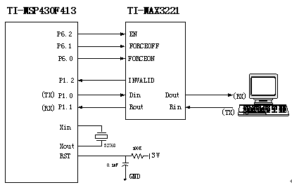
Figure 3 MSP430F413 ultra-low power serial communication circuit schematic
3.2 The solution of ultra-low power consumption selects the device of low power consumption, and it also needs reasonable control to achieve the lowest energy consumption [1]. For this application, MSP430 is in a slave working state. For this application, the following scheme can effectively reduce energy consumption: After the initialization procedure is completed, set the MSP430F413 to work in power mode 4 and wait for the interrupt of the P1.2 pin. At this time, the CPU will shut down, and its energy consumption is the lowest (0.1μA). On the other hand, the initial control MAX3221 enters the state of automatically adjusting energy consumption. If the microcomputer does not send a signal, that is, the Rin input is invalid, both the driver and the receiver will shut down and enter a very low power consumption standby state (1μA).
When the microcomputer sends a signal, that is, the Rin input is valid, the receiver will automatically turn on and generate a valid INVALID signal. This signal will trigger the interrupt of P1.2 pin. Set the power consumption mode of the MSP430F413 to Mode 3 (power consumption current 0.7μA) in the interrupt handler. At this time, the ACLK clock with a frequency of 32768 can be used to complete the low-speed serial communication task. After receiving and processing the data of the microcomputer, the result needs to be returned to the microcomputer. At this time, you can turn on the driver of the MAX3221 and turn off the receiver to complete the work. When the transmission is completed, the MSP430 and MAX3221 can be set to the lowest power consumption state ready to receive information.
Using the above method can achieve very low power consumption while meeting serial communication.
Table 1: MAX3221 transceiver working control and working state comparison table
| Work and energy consumption status | FORCEON | FORCEOFF | EN | Receiver input signal Rin | Drive status | Receiver status |
| Lowest power consumption in full standby | X | 0 | 0 | X | shut down | activation |
| X | 0 | 1 | X | shut down | shut down | |
| Manual adjustment of energy consumption in normal working conditions | 1 | 1 | 0 | X | activation | activation |
| 1 | 1 | 1 | X | activation | shut down | |
| Device automatically adjusts energy consumption in self-care state | 0 | 1 | 0 | effective | Automatic activation | activation |
| 0 | 1 | 1 | effective | Automatic activation | shut down | |
| 0 | 1 | 0 | invalid | shut down | activation | |
| 0 | 1 | 1 | invalid | shut down | shut down |
Note: The driver converts the MOS level to RS232 level, the receiver converts the RS232 level to MOS level
4 Conclusion Using the above design methods and circuits, the serial communication between the MSP430 and the microcomputer is well achieved, and a very ideal power consumption level is achieved. Practice has proved that this method is very effective for serial communication of MSP430 series microcontrollers without hardware UART, and provides a feasible solution for other types of MSP430 microcontrollers that need to expand the serial port. In addition, the ultra-low power circuit design method in this article is a good solution for power-sensitive applications.
references:
[1] Brian Merritt. Ultralow Power Thermostat ([R]). Texas, USA: Texas Instruments Incorporated, 2001.
[2] MAX3221 3-V TO 5.5-V single-channel RS-232 line driver / receiver (Manual). Texas, USA: Texas Instruments Incorporated, 2001.
[3] Hu Dake. The principle and application of MSP430 series ultra-low power 16-bit microcontroller, Beijing Aerospace Press, 2001.
[4] Hu Dake. MSP430 series FLASH ultra-low power 16-bit microcontroller, Beijing Aerospace Press, 2001.
Appendix: Program code for asynchronous serial communication using capture comparison:
; ------------------------------------------------- -----------------------------
Description:
The hardware connection is shown in Figure 3. P1.0 is used as the sending pin and P1.1 is used as the receiving pin.
Tbit1 is 1-bit interval data (T1), and Tbit_5 is half-bit interval data. (From formula 1)
RTbuff is a unit for receiving and sending buffer words, which stores received and sent data
Counter is the counter used in the sending and receiving process
; ------------------------------------------------- -----------------------------
Send subroutine
| MOV | & TAR, & CCR0 | ; Store the current timer value in CCR (T0) |
| ADD | # Tbit1, & CCR0 | ; Add 1 bit time interval to CCR (T0 + T1) |
| RLA | RTbuff | ; Shift the byte data sent with one bit to the left, construct the lowest bit as the start bit |
| BIS | # 0200h, RTbuff | ; Put the stop bit data into the 10th bit of the word to be sent |
| MOV | # 10, Counter | ; Initialize data frame counter to 10 |
| MOV | # OUTMOD0 + CCIE, & CCTL0 | ; Mark sending status, open capture compare interrupt, start sending |
| RET | ; Return |
; ------------------------------------------------- -----------------------------
Reception preparation subroutine
| MOV | # 08, Counter | ; Initialize the received data counter to 8 (receive a byte of data) |
| MOV | # SCS + CCIS0 + OUTMOD0 + CM1 + CAP + CCIE, & CCTL0 | ; Initialize capture control word, |
| ; Set to falling edge capture mode, mark receiving status, turn on interrupt, start receiving | ||
| RET | ; Return |
; ------------------------------------------------- -----------------------------
Capture the interrupt service routine of compare module 0
; ------------------------------------------------- -----------------------------
| ADD | # Tbit1, & CCR0 | ; Add 1 bit time interval to CCR0 | |
| BIT | # CCIS0, & CCTL0 | ; Judge the receiving and sending status | |
| JNZ | UART_RX | ; Is the receiving state, transfer to receiving processing | |
| UART_TX | CMP | # 00h, Counter | ; Is the sending state, to determine whether the frame transmission is over |
| JNE | TX_Next | ; No end, go to send | |
| BIC | # CCIE, & CCTL0 | ; End of frame transmission, close interrupt | |
| RETI | ; Interrupt return | ||
| TX_Next | RRA | RTbuff | ; To be sent into the carry bit C |
| JC | TX_One | ; Is this bit 1? Jump | |
| BIS | # OUTMOD2, & CCTL0 | ; This bit is 0, send 0 | |
| JMP | TX_nxt2 | ; Jump to continue processing | |
| TX_One | BIC | # OUTMOD2, & CCTL0 | ; This bit is 1, send 1 |
| TX_nxt2 | DEC | Counter | ; Send frame counter decremented by 1 |
| RETI | ; Interrupt return | ||
| ; | |||
| UART_RX | BIT | # CAP, & CCTL0 | ; Determine if the start bit is captured |
| JZ | RX_Bit | ; Received is not the start bit, transfer to processing | |
| RX_Start | BIC | # CAP, & CCTL0 | ; The start bit is captured and the status is changed to the comparison mode |
| ADD | # Tbit_5, & CCR0 | ; Add another half bit time interval (T0 + T1.5) to achieve 1.5 time interval | |
| RETI | ; Interrupt return | ||
| RX_Bit | BIT | # SCCI, & CCTL0 | ; Store the received bit in carry bit C |
| RRC | RTbuff | ; Move the received bit into the send-receive buffer word | |
| RX_Test | DEC | Counter | ; Receive data counter decremented by 1 |
| JNZ | RX_Next | ; Determine whether all data bits are received, and no jump to subsequent processing | |
| BIC | # CCIE, & CCTL0 | ; Receive all data bits, close capture compare interrupt | |
| RX_Next | RETI | ; Interrupt return | |
A manual pulse generator (MPG) is a device normally associated with computer numerically controlled machinery or other devices involved in positioning. It usually consists of a rotating knob that generates electrical pulses that are sent to an equipment controller. The controller will then move the piece of equipment a predetermined distance for each pulse.
The CNC handheld controller MPG Pendant with x1, x10, x100 selectable. It is equipped with our popular machined MPG unit, 4,5,6 axis and scale selector, emergency stop and reset button.
Manual Pulse Generator,Handwheel MPG CNC,Electric Pulse Generator,Signal Pulse Generator
Jilin Lander Intelligent Technology Co., Ltd , https://www.jilinlandermotor.com