Fan Liang, Wang Di, Chen Xuefeng, The 28th Institute of China Electronics Technology
Keywords: PowerPC; FPGA; navigation radar; network transmission
0 Preface
As a navigation device, a marine navigation radar plays an important role in the entry and exit of ships and collision avoidance through display and tracking of radar echoes by display terminals. At present, navigation radar signals usually use dedicated cables to realize point-to-point transmission between radar transceivers and display terminals. Generally, a navigation radar only has one display terminal. In some specific cases, radar echoes need to be displayed and tracked in multiple places. This need can be met by adding dedicated navigation radar echo signal splitters. Since the echo signal output by the navigation radar is generally an analog signal, adding a signal splitter slightly affects the quality of the navigation radar echo signal, and the transmission distance is also limited.
With the development of informatization technology, some navigation radars currently transmit radar signals to the display terminals at the front end of the transceiver equipment. For example, Raymarine uses the custom SeaTalk hs protocol to use 100M networks to realize radar echoes. Remote transmission and sharing display. However, the small amount of data transmitted through the 100M network is not conducive to display and tracking processing of the display terminal. By real-time conversion of radar echoes into network data, radar echo multi-node display and high-quality tracking processing can be realized.
1 system architecture
In order to achieve non-destructive real-time conversion and transmission of navigation radar signals, FPGA+PowerPc architecture is used. FPGA realizes real-time lossless packetization of signals such as digital radar trigger, azimuth, working mode, and radar echo after A/D sampling. PowerPC, as a core processor, has strong communication capabilities, adopts an embedded Linux operating system, and passes radar data through thousands of Mega-networks output in real time over UDP. The system structure is shown in Figure 1.

Figure 1 System Structure
Because in the PowerPC embedded Linux system, the network interface chip configuration and operation of more mature applications, not repeat them here. The following mainly introduces the radar data packet inside FPGA and the data transmission between LocalBUS of FPGA and PowerPC.
2 FPGA data package
2.1 FPGA Introduction
FPGA selects EP1S25 of Strata series of Altera Company, this FPGA has 25660 logic units, have 1.9Mb internal memory space. The internal storage of the FPGA includes three types of memory blocks: M512, M4K, and M-RAM. All of them can be used as single-port RAM or single-port RAM to facilitate data storage and read operations.
2.2 Radar data package
When radar data packs are used, one triggers all radar information to be packaged, including echo data and radar speed, antenna position, and working mode. The radar echo sampling clock is selected according to the operating mode, typically 20 MHz for narrow-pulse (close-range) sampling clock, 10 MHz for medium-pulse (mid-range) sampling clock, and 5 MHz for long-pulse (remote-range) sampling clock. The sampling bits are all 8 bits.
Given the trigger length of different working modes of the radar, the total information capacity m within one trigger can be calculated:
m = trigger length / clock sampling bits + extension bits.
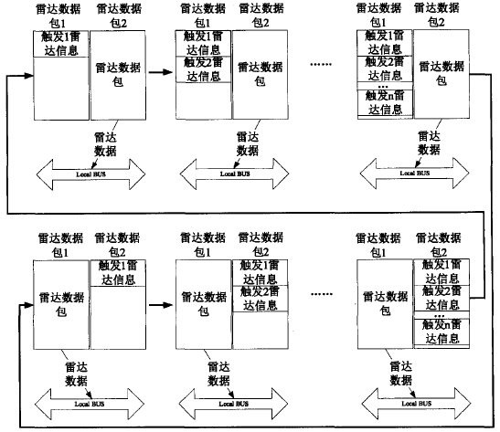
Radar data is transmitted as UDP, with a maximum of 64K bytes per UDP packet. In order to improve the transmission efficiency, n triggering radar data are stored in each radar data packet, n=INT(64K/m), as shown in FIG. 2 .

Figure 2 shows the radar data package
2.3 PowerPC data read package
After the radar data packet group package is completed, it informs LocalBUS to read the data in the radar data packet, and through the ping-pong operation, the group packet and LocalBUS read data are cyclically performed, as shown in FIG. 3 .

Figure 3 Reading of radar data packet data
3 PowerPC System Design
The PowerPC processor uses Freescale's MPC8377E. The processor integrates the e300c4 processor core. It has 32Kbytes of instruction cache and 32Kbytes of data cache on the chip. The work frequency is up to 800Mhz. The MPC8377E can support 2GB DDR2 memory. The local LocalBus bus of MPC8377E expands a NOR FLASH as the storage space of the system. Its role is to store bootloader, operating system kernel, file system. Through the 88E1111 network chip access Gigabit Ethernet, as shown in Figure 4.

Figure 4 PowerPC hardware system architecture
The PowerPC processor runs a radar data read-and-forward program and a LocalBus bus driver.
The radar data reading and forwarding program reads the radar data through the LocalBus bus driver and packs it into a fixed format and then outputs it through the network.
The LocalBus bus driver implements functions such as master-slave device number application, device registration, FPGA address function mapping, and device hardware control. The driver organizes the specific implementation functions of the device through a file_operations structure, and uses the mmap() address mapping function to implement the mapping from the underlying physical address of the Linux kernel to the virtual address of the application layer. The kernel uses the address mapping to achieve the upper radar data reading and forwarding program and directly access the LocalBus physical address function.
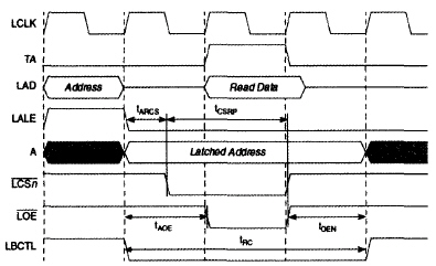
The LocalBus bus driver configures the LocalBus bus as a General Chip Select Mechanism (GPCM), 32 Bit Bus. Radar data reading and retransmitting procedure Local Bus read timing when reading the radar data through LocalBus is shown in Figure 5. The parameters tRC, tARCS, tCSRP, tAOE, and tOEN can be flexibly configured by software. The timing is simple, and the FPGA design is easy to implement.

Figure 5 LocalBus read timing
4 Conclusion
This design realizes the networked data transmission of navigation radar signals, which facilitates the complex data processing at the back end. It has been used for a long time in the project and the design is stable and reliable. And this technology can be applied to radars of other single-pulse systems, such as airport surveillance radars, port surveillance radars, etc., and has good reuse and promotion value.
A Bridge rectifier is an Alternating Current (AC) to Direct Current (DC) converter that rectifies mains AC input to DC output. Bridge Rectifiers are widely used in power supplies that provide necessary DC voltage for the electronic components or devices. They can be constructed with four or more diodes or any other controlled solid-state switches.
Bridge rectifiers,Ultra Fast Switching Diodes,Fast Recovery Diode,Fast Switching Diodes,Diode Bridge Rectifiers
Changzhou Changyuan Electronic Co., Ltd. , https://www.cydiode.com