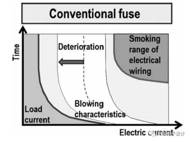
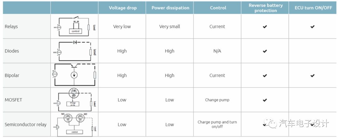
Huzi gave me some summary materials for the exchange, which was very good. I will extract it and share it with you. The general background is that in the entire intelligent power distribution unit, relays are replaced by MOSFETs. The 12V power distribution architecture, especially electric vehicles, has begun to change due to changes in the entire system. Traditional power distribution architectures are limited by relays and fuses:
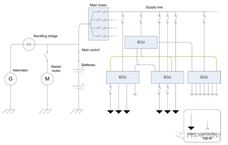
As shown below:
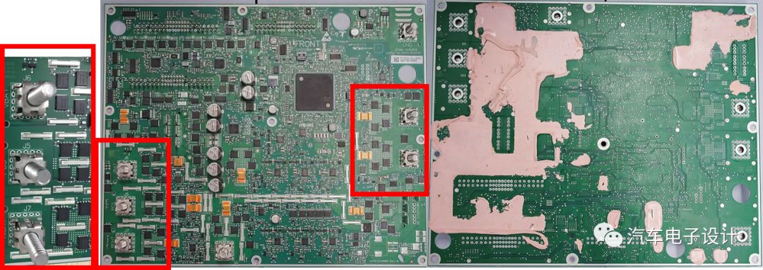
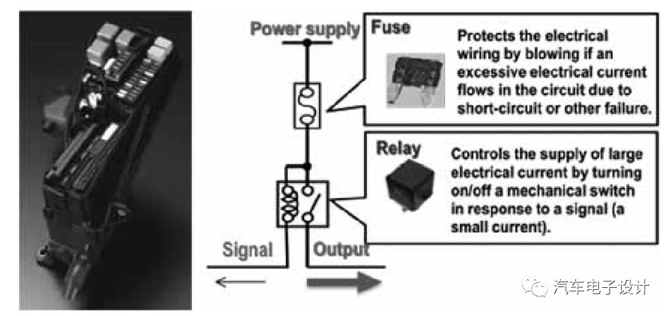
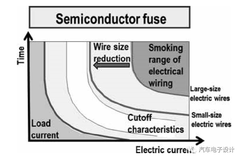
A large part of the design of fuse + relay for power distribution is replaced by MOSFET management circuit
This path of development is getting faster and faster. With the rapid development of MOSFET, only a single chip can replace many components such as relays, fuses, relay drivers, etc. From the point of view of the chip, MOSFET switches are extremely durable and are not afraid of dust, shock and vibration, so configuration and assembly It has more flexibility when it comes to components. The main advantages are:
1) Differences in behavior during overload, when the fuse is damaged and needs to be replaced, the application will not work. MOSFET-based switches can be reset and restarted through software;
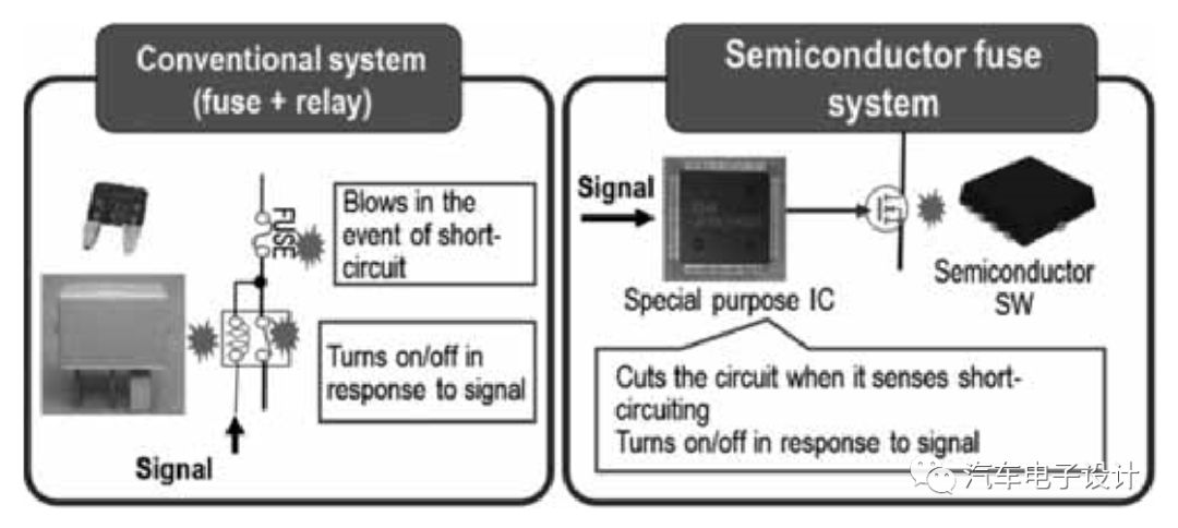
2) At the level of withstand short circuit, because it is a closed loop system, it can withstand more short circuit cycles
3) The relay will produce a little noise, and the noise of the MOSFET is almost no noise when the state is switched.
Remarks: The most important thing here is the protection of wiring harness short-circuit. For electric vehicles, apart from the battery, there is the most electrical short-circuit problem. Through the wiring harness model, the entire short-circuit state can be carefully and carefully set, and the current can be judged early Electrical short circuit (especially intermittent)

Short circuit calculation analysis of wiring harness
As shown in the figure above, the traditional fuse design has actually achieved a certain level, and it is more difficult to proceed further. Through the design of this power distribution box, a lot of work can be liberated mainly for the wiring harness design
Remarks: From a control point of view, the difference is mainly in the control part, and a large part of it was done in the form of HSD packaging before.
The following is written by Huzi, I made some excerpts and quotes, and extracted the HSD part
The first part is from HSD switch design considerations
â—†What is the normal current of the load?
â—†What is the maximum current?
â—†What is the working environment temperature of the load? How much is the limit temperature test?
â—†Is the load capacitive? What is the inrush current if it is capacitive?
â—†Is the load inductive? In perceptual terms, the energy when it is turned off?
â—†How to control the load? ON/OFF mode (no freewheeling, pay attention to overvoltage protection, need to protect GD, GS back-to-back zener tubes), PWM mode (with freewheeling, no overvoltage protection for GD, GS) Note: ON/OFF mode And PWM mode refer to SMTC 2800 017 circuit port design purpose
â—†If the system is ground wire open, what impact will it have on the load?
â—†For heat dissipation method, do you need to add a heat sink according to the parameter calculation? (The area size of the copper foil in the through-hole method on the PCB)
â—†Does the load need to be diagnosed: if so, what are the diagnoses? Over current, over voltage, over temperature or short circuit.
â—†Whether the load has the following applications: reverse battery connection, load dump, overvoltage, overcurrent, etc.
â—†Load dump: If the load dump exceeds the maximum rating of VCC, the Did transient suppression diode must be added.
The second part is the difference between HSD and LSD:
â—†On-resistance: The on-resistance of NMOS is smaller than that of PMOS under the same conditions (the conduction speed of electrons is faster than that of holes, which affects the on-resistance). In order to pursue low on-resistance, some HSD drives Application, using charge pump plus NMOS to complete the application of PMOS as HSD, the price is high, the drive is more complicated.
â—†Sampling circuit: For HSD protection, current sampling is required, and differential configuration is needed to realize current sampling; for LSD, a single-ended configuration can be used. Since the cost of the differential circuit is higher than the cost of using single-ended, in this sense, LSD has a cost advantage over HSD.
â—†Wire system requirements: most of the loads in the car are negative grounding. The advantage of using HSD to supply power to the load is that one end of the load is directly connected to the chassis ground, and the other end only needs one wire to supply power to the load, which saves The cost of the system.
â—†The influence of the failure on the system: This is based on the requirements of the system, which load failure is selected. In the aircraft failure type, if the load fails, the safest way is to let the load continue to run; while for the load application of the car, the opposite is true.
Advantages and disadvantages of HSD driver configuration:
â—‡1 Wires in the system
â—‡Short circuit to ground will not damage the load
â—‡load corrosion unlikely (connect to ground)
â—‡ Simple connection is more robust (single line)
â—‡Internal circuit (complex design and high cost); external wiring (single wire, simple wire cost reduction)
For example: In ECM control, the switch that controls the oil pump is HSD. This is because in most cases, when the drive module fails, the oil pump is turned off. This design is very beneficial when there is a car accident or system failure. .
As shown in the circuit:
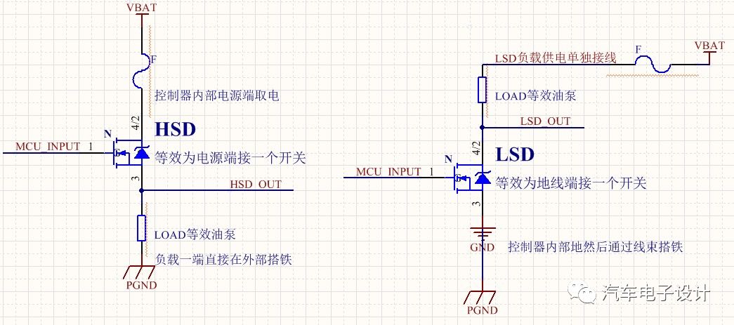
The control oil pump is controlled by the HSD switch on the power end. When the car encounters a dangerous situation, the power supply is directly cut off by the control module to avoid a short circuit between a certain point of the fuel tank and the other end of the load (for low-side control, equivalent oil pump control) The circuit is only a ground switch, and the other end of the oil pump load is connected to normal current); therefore, LSD control is more likely to suffer from short-circuit hazards. LSD short-circuit will cause the load to be permanently turned on. HSD short-circuit only causes stress on the switch, compared to battery voltage , Grounding is more vulnerable to short-circuit hazards, so HSD switches are safer than LSD switches.
HSD: HSD_OUT short-circuit to ground only causes stress to the switch (MOS tube), which can be understood as an insurance for the power supply
LSD: If LSD_OUT is short-circuited to ground, the load will be permanently turned on, so it is very dangerous for oil pump control (when the car encounters a dangerous situation).
Summary: To start, from the perspective of automotive electronics, development and innovation have also started with the intelligentization of vehicles. It is difficult to make money from a module or component in China.
Dongguan Guancheng Precision Plastic Manufacturing Co., Ltd. , https://www.dpowerchargers.com