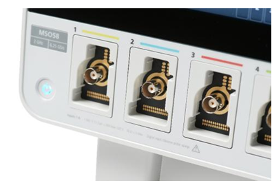
Mixed-signal oscilloscopes first came out in 1993 and have two analog channels with 8 or 16 digital channels. In the next few years, mainstream MSO, as an indispensable debugging tool for embedded system designers, basically locked the number of channels at 2 or 4 analog channels, plus 16 digital channels. Embedded designers use MSO because it has expanded from being able to view 2 or 4 signals to being able to view up to 20 signals without having to resort to the last tool-a logic analyzer.

Although this number of channels has been widely accepted by the market for a long time, is it still suitable for today's embedded systems? For oscilloscope manufacturers and embedded system designers, this is a question worth thinking about. The manufacturer must know whether it provides the test function that the customer actually needs and is willing to pay for it. Designers need tools suitable for the job.
Thinking of this issue has promoted the implementation of multiple scientific research projects. Embedded system engineers from all over the world are investigating the issue of the number of oscilloscope channels more deeply. The latest 5 series MSO reflects the results of these studies in many places, increasing the number of analog channels provided to 6 or 8, and providing 8 to 64 digital channels. In addition, the digital channels can be reconfigured during operation.
In view of the impressive achievements of 4-channel MSO in the past few years, it can be said that the traditional number of analog channels and digital channels can fully meet the needs of most embedded designers. More precisely, designers strive to make 4 Enough channel. But a large percentage of engineers (35% in our research) claim that the ideal number of analog channels they need is 8.
In the past, when these engineers needed more than 4 analog inputs, they would try to use two oscilloscopes at the same time. This method of "cascading" multiple oscilloscopes brings multiple challenges. For synchronous acquisition, multiple oscilloscopes must be triggered at the same point in time, which not only places requirements on cables (or dual probes), but also requires creative trigger settings. In addition, it is difficult to compare the data on the two display screens, so many engineers obtain data from two oscilloscopes and then use a computer to combine the waveforms for evaluation. Even if the two oscilloscope models are exactly the same, this synchronization will still take a long time, and if you are using a different oscilloscope model, then the problem will be more.
In terms of digital channels, facts have proved that reducing the number is as important as increasing the number. In some cases, many engineers have a great sense of frustration because they are forced to buy 16 digital channels when in fact only 8 digital channels are needed. In our research, about 75% of the respondents claimed that the number of digital channels they want is not 16. Some people want more, and some people want less.
For embedded system designers, flexibility is more important than the number of channels among many features of oscilloscopes. Our research found that 79% of embedded engineers hope that oscilloscopes are "future-oriented" and have a variety of functions to meet the various needs of design teams under tremendous pressure.
When we discuss with embedded designers at which stage more channels and more flexibility are needed, the most common answer is during system-level debugging. When multiple subsystems begin to merge together, multiple processors, multiple power supplies, multiple serial buses, and multiple I/O devices, system-level viewing capabilities will become critical at this time. In the traditional debugging method using an oscilloscope, engineers have to use 2 channels or 4 channels to capture data multiple times, trace back the signal path, and find the root cause of the problem. Many systems today have to process inputs from multiple sensors, drive multiple actuators, and communicate through multiple buses at the same time. Traditional debugging methods may encounter many problems. These embedded computing systems include sensors, accelerators, processing capabilities, and communications, forming distributed smart devices in the growing Internet of Things (IoT).
Our research found that another pain point for embedded engineers stems from the surge in the number of power supplies in today's systems. To optimize power consumption, performance, and speed, even a relatively simple system may have a 12 V overall power supply, multiple 5 V power supplies, a 3.3 V power supply, and a 1.8 V power supply. Checking and debugging the power-on and power-off sequence of these power supplies, especially the relationship with other control signals or status signals on the circuit board, requires more channels and more tests.
Some creative engineers report that they use variable thresholds on digital MSO channels to verify power supply sequence. In this case, they set the threshold of the digital channel to be slightly lower than the nominal voltage of the power supply, and use this setting to generate "timing diagrams" of power, reset lines, interrupts, status lines, etc. This method has an obvious flaw, that is, the power is represented by a binary waveform, ignoring the analog characteristics of the signal. Most engineers prefer to use analog channels to perform this kind of testing and debugging.
For many applications, a traditional configuration of 4 analog channels/16 digital channels may be sufficient. But if we encounter new problems, and we will definitely encounter new problems, then it is best to know that there are finally some other options to choose from.
Suizhou simi intelligent technology development co., LTD , https://www.msmvape.com