1 Introduction
The motor control system is an important part of the electric car. The reliability of the motor control system is especially important for the safety of electric vehicles. The vehicle safety integrity level defined by ISO26262 divides the safety objectives of the vehicle from low to high into four grades: ASIL A, ASIL B, ASIL C and ASIL D. According to the functional safety requirements of the vehicle safety target and corresponding to the relevant components, it can be known that the functional safety requirements of the motor control system must meet at least the safety level of ASIL C to meet the functional safety objectives of the vehicle. However, the traditional motor controller is a single motor control chip as a processor, and it is often difficult to achieve ASIL C. Therefore, this paper presents a design scheme for safety monitoring of pure electric vehicle motor control system. By adding a safety monitoring chip CIC61508 to monitor the motor control chip, the safety level of the system is improved to meet the ASIL C standard. Meet the growing demands of automotive safety.
2 security monitoring function system architecture
The safety monitoring function of the pure electric vehicle motor control system described in this paper is divided into two levels - hardware level and software level.
Hardware-level safety monitoring function system architecture includes motor control chip for controlling motor operation, safety monitoring chip, power monitoring module for monitoring motor control chip power supply voltage, voltage monitoring module for monitoring DC voltage, current monitoring module for monitoring motor phase current, monitoring Temperature monitoring module for inverter temperature and hardware watchdog module.
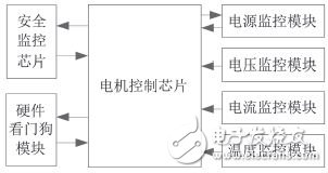
Figure 1 Hardware-level security monitoring structure diagram of motor control system
Software-level security monitoring functions include voltage monitoring, current monitoring, temperature monitoring, speed monitoring, torque monitoring, power monitoring, mode monitoring, communication monitoring, and security monitoring call procedures implemented in the security monitoring chip.
3 software and hardware design
3.1 Hardware System Design
3.1.1 Selection of motor control chip
The motor control chip selects the TC1782 high-performance microprocessor from Infineon's 32-bit TriCore series. TC1782 has good performance in power consumption, computing power, storage space, digital analog input and output, and CAN communication, and has high cost performance, which is very suitable for electric vehicle motor control system.
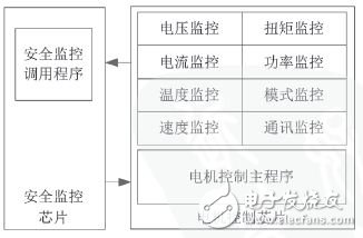
Figure 2 Motor-level control system software-level security monitoring structure
3.1.2 Selection of Security Monitoring Chips
The security monitoring chip uses the Infineon CIC61508 chip. The CIC61508 safety monitoring chip is small in size and saves space when used. It is a cost-effective choice for safety applications. The safety monitoring circuit monitors the operation of the motor control chip by detecting common fault modes such as the clock, power supply, and temperature-related calculation errors of the motor control chip.
CIC61508
3.1.3 Hardware Circuit Design
The motor control chip TC1782 communicates with the safety monitoring chip CIC61508 and the resolver decoding chip AU6803 through two sets of SPI respectively; receives or transmits digital quantity through GPIO; sends six PWM signals to the gate drive chip through PWM channel; samples current and voltage through ADC module , temperature and other information; communicate with the bus through the CAN module. The hardware circuit also includes a power module and a watchdog module. The hardware circuit schematic is shown in Figure 3.
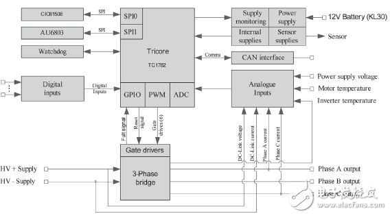
Figure 3 hardware circuit schematic
3.2 Software Design
3.2.1 Design principle
The safety monitoring function proposed in this paper ensures the normal operation of the motor control system through two levels of hardware-level and software-level monitoring, including monitoring of the motor load and monitoring of the motor control chip.
The principle of the motor load monitoring function is to judge whether the motor load is working in a normal state by sampling the current, voltage, temperature, position and other signals and fault information from the hardware monitoring circuit. Once an abnormality is detected, the motor control system enters. Troubleshooting procedure.
The safety monitoring function of the motor control chip is completed by the self-test of the motor control chip and the CIC61508 security monitoring chip. The motor control chip will self-test after power-on and test whether the configuration of each module is normal. If it is abnormal, it will enter the fault handling program; during the normal operation of the program, the motor control chip will periodically configure, memory and control each module. The task is tested. At the same time, the motor control chip sends a specific test task to the CIC61508 safety monitoring chip test, and feeds the test result back to the motor control chip. The motor control chip compares the results of its own operation with the feedback results to determine whether the motor control chip is working properly.
3.2.2 Concrete implementation
The motor control chip samples the sensor supply voltage, the chip supply voltage, the bus current, the bus voltage, the phase currents of the A and C phases, the motor temperature, the inverter temperature, etc. through the ADC module; and receives the fault information from the hardware monitoring circuit through the GPI interface. Mainly motor control chip power supply voltage fault, DC voltage overvoltage fault, motor phase current overcurrent fault, inverter over temperature fault, inverter saturation fault, position sensor fault, etc.; receiving motor position information and safety monitoring through SPI Chip information. The motor control chip sends the test task to the safety monitoring chip through the SPI. The safety monitoring chip feeds the test result back to the motor control chip for comparison. If the test result is consistent, it proves that the motor control chip works normally, otherwise it enters the fault handling procedure.
CIC61508
4 working process
The main flow chart of the motor control system safety monitoring algorithm is shown in Figure 4. When the controller is turned on:
The first step is to initialize the modules of the motor control chip so that each module is configured in the normal working state. After the initialization is completed, the initialization state of each module is judged. If there is a module that fails to initialize, the module fault code is reported, and the fault is entered. mode.
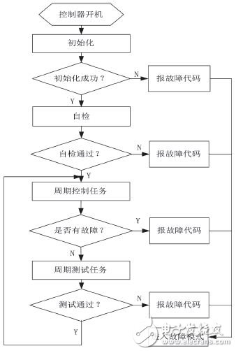
Figure 4 Security monitoring algorithm flow chart
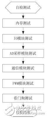
Figure 5 Self-test algorithm flow chart
In the second step, the modules of the motor control chip are self-tested. As shown in Figure 5, the self-test program tests the memory, IO module, AD sampling module, communication module, PWM module, watchdog, etc. The specific test is as follows:
Memory test: mainly test the RAM, ROM, and Flash used by the program, check whether the RAM works normally, whether the software in the ROM is changed, and whether the reading is normal;
IO module test: Test whether the IO module works normally, and whether the IO control unit is configured correctly;
AD sampling module test: Test whether the AD sampling module works normally, the sampling frequency, the channel selection is correct, and the control unit setting is correct;
Communication module test: Test whether CAN communication, SPI communication module works normally, whether the baud rate setting is correct, whether the module configuration is correct, and whether the security monitoring chip communication is normal, and whether the security monitoring chip works normally;
PWM module test: Test whether the PWM module works normally, whether the clock setting is correct, and whether the output channel configuration is correct;
Watchdog test: Test the watchdog timing, whether the time configuration is correct, and whether it works properly.
If these tests pass, it means that each module works normally, the system configuration is correct, and the system can continue to run if the system meets the operating conditions. If the test fails, you need to record the module error code that fails, the system enters the fault mode, and the error code is put. Send out via CAN.
When these tests pass, the system enters the normal cycle operation mode; if the self-test fails, the system reports the self-test failure code and enters the failure mode.
The third step is the system cycle control task. All work on motor control is done in this part, which is also part of the traditional motor control. Power supply monitoring, voltage monitoring, current monitoring, temperature monitoring, speed monitoring, and external watchdog monitoring are all completed in this part. If the system is faulty, the fault code is reported and the fault mode is entered; if the system goes to the next step.
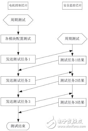
Figure 6 Cycle test algorithm flow chart
The fourth step, the system cycle test task, is shown in Figure 6. The cycle test task is performed simultaneously in the motor control chip and the security monitor chip. After the cycle test task starts, first check the configuration files of each module of the motor control chip, test whether the configuration of each module is illegally changed, whether it is consistent with the normal configuration; then send a specific test task to the security monitoring chip, and the security monitoring chip receives After the task, the test results are fed back to the motor control chip according to a predetermined algorithm, and the test tasks can be increased or decreased according to actual needs. The motor control chip judges whether the program runs normally according to the test result of the received safety monitoring chip, and whether there is an unexpected operation result. If the test result passes, the system enters the cycle operation mode, the cycle operation system cycle control task and the cycle test task. If the test fails, the fault code is reported and the system enters the fault mode.
5 Conclusion
The motor drive system safety monitoring function not only can monitor the running condition of the motor load in real time, but also monitor the running state of the motor control chip, find faults and deal with them in time, comprehensive fault diagnosis and high coverage, which greatly improves the operation of the motor drive system. Safety and reliability.
Micro Data Line is a portable version of the Data Line 2.0 standard. The Micro data cable has a smaller interface than the Mini data cable used in some mobile phones, and is the next generation of Mini data cable specifications. This data line supports OTG and is 5PIN like MINI data line. Micro-usb supports OTG and, like Mini-USB, is also 5PIN. The definition of Micro series includes Micro-B series slots for standard equipment; Micro-ab slots for OTG devices; Micro-a and micro-B plugs, and cables. The Micro series is unique in that they include a stainless steel case that can be inserted and removed for 10,000 times. Compared with the Usb Cable Type C, the Type-C interface is plugable, but the Micro USB interface is not.
Micro-usb connectors are smaller and space-saving than standard USB and Mini-USB connectors, with up to 10,000 plug and remove life and strength, and a blind plug structure design. The Micro-USB standard supports the OTG functionality of current USB, that is, in the absence of a host computer (for example, a personal computer). Data can be transferred directly between portable devices, compatible with USB1.1 (low speed: 1.5Mb/s, full speed: 12Mb/s) and USB 2.0(high speed: 60Mb/s). Provides data transmission and charging at the same time, especially suitable for high-speed (HS) or higher data transmission, is the best choice for connecting small devices (such as mobile phones, PDAs, digital cameras, digital camcorders and portable digital players, etc).

Micro Usb Cable,Usb Charging Cable,Micro Usb C Cable,Braided Micro Usb Cable
Henan Yijiao Trading Co., Ltd , https://www.yjusbcable.com