As a device that converts electrical energy into mechanical energy, the motor generally works under high-speed rotation. However, how to let this dislocated wild horse slam the horse to let the prodigal son turn back, the key moment to stop and stop learning is not as simple as imagined. There is a lot of knowledge about motor operation. Let's take a look at the doorway that stops the motor.
The way of civil and military, one by one. The gentleman can handle things. The same is true for the control of the motor. It is necessary to let the motor go into the working state when it is said to go away, and also to let the motor stop when it stops. If the electric car can't brake at any time, the elevator can't stop at the designated floor as desired, and the crane can't hang the suspended cargo in the air stably, what kind of ridiculous and chaotic scene?

How to make the motor rotate, the answer is relatively simple, give him electricity to let him output kinetic energy. But letting it stop at a critical moment is not so simple, how can the motor go to the climax and stop immediately?

In general, the braking of the motor is divided into two types, which are not technical and technical. The technical content is that the mechanical brake is simple and rough, and a large brake pad or brake can solve the problem. However, it is not reliable to rely on friction and friction to make custom movements. The brake pads may be dangerous after being worn. So what is the technical brake method? The technical content is called electric brake. Compared with the violent mechanical brake, electric brake is a kind of internal effort. Electric braking is subdivided into: reverse braking, dynamic braking and regenerative braking.
· Reverse braking: Add a back electromotive force to the motor. The direction of rotation of the magnetic field is opposite to the direction of the rotor. The motor is stopped by the reverse torque. This method has high control requirements and may be reversed if you are not careful. Need to pay attention.
· Energy consumption braking: DC energy is applied to the motor to consume kinetic energy. The braking effect and accuracy of this method alone are not ideal.
· Regenerative braking: The motor working condition of the motor is converted into the working condition of the generator, and the kinetic energy of the flying is converted into electrical energy for storage, energy saving and low carbon. This method is widely used in electric vehicles.
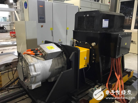
Therefore, when designing the MPT motor test system, Zhiyuan Electronics also selected the energy feedback scheme of the motor driver for the design of the motor safety shutdown. Energy can be recovered while maintaining accuracy and response time, and many birds are so touching. When the feed characteristic test is performed separately, the motor is converted into a mode of outputting electric energy, and the electric energy to be generated by the bidirectional power supply in the system is fed back to the grid. At this point, the power analyzer synchronously collects the data of the voltage and current and the torque and speed sensor at both ends of the driver, and the feed efficiency can also be clearly tested.

In the national standard, how is the feed characteristics test defined?
During the test, the driven motor system is driven by the prime mover (dynamometer) and is in the feeding state. According to the experimental purpose and the measured parameters, the motor controller is driven by the DC bus voltage set by the motor controller. The motor is fed with a corresponding operating speed and torque load.
The load speed value is selected from more than 10 measurement points. The selected points should include the following special points:
· rated working speed point;
· Maximum working speed point;
· The minimum operating speed point corresponding to the continuous power;
· Other specially defined work points, etc.
Select more than 10 measurement points for the measured torque value. The selected points should include the following special points:
· the point at the continuous torque value;
· the point at the peak torque (or maximum torque) value;
· a point on the continuous power curve;
· the point on the peak power (or maximum power) curve;
· Other specially defined work points, etc.
Record the DC bus voltage, DC bus current, AC voltage of each phase of the drive motor, AC current, and the speed and torque of the drive motor shaft when the feed state is recorded. Calculate the power of the motor and controller at the same time. Feed efficiency, etc.
In fact, it is not just the brake and feed energy of the motor. For modern motor production and design, it is necessary to pay attention to the control performance of the motor in all aspects of motor operation. While understanding the steady-state characteristics of the motor, you should also pay more attention to the dynamic characteristics of the motor. The control of the motor's rotational speed torque response and control accuracy can also be accomplished by the Zhiyuan electronic MPT motor test system. An excellent motor must be walked away and stopped. This depends on the advancement of technology, but also from the tireless pursuit of our engineers.

Directional antennas are a vital component in wireless communication systems, renowned for their ability to transmit and receive signals with a high degree of directionality. These antennas are designed to focus their radiation pattern in a specific direction, enhancing the signal strength in that direction while minimizing interference and noise in other directions. Directional antennas come in various shapes, sizes, and configurations, each tailored to meet specific communication requirements. In this article, we will delve into the classification and key features of directional antennas.
Classification of Directional Antennas
-
Beamwidth and Gain
- Narrow Beamwidth Antennas: These antennas have a narrow radiation pattern, resulting in a high gain in a specific direction. They are ideal for long-distance communication and applications requiring high directionality, such as satellite communication, point-to-point microwave links, and radar systems.
- Medium Beamwidth Antennas: Offering a balance between gain and coverage, medium beamwidth antennas are commonly used in cellular networks, Wi-Fi access points, and other applications where a balance of range and coverage area is crucial.
- Wide Beamwidth Antennas: With a wider radiation pattern, these antennas provide broader coverage but with lower gain. They are suitable for applications where wide-area coverage is essential, such as TV broadcasting, emergency communication systems, and some types of IoT networks.
-
Polarization
- Linearly Polarized Antennas: These antennas radiate energy with a linear polarization, either horizontally or vertically. They are commonly used in terrestrial communication systems due to their compatibility with most transmitting and receiving equipment.
- Circularly Polarized Antennas: Circular polarization occurs when the electric field vector rotates in a circular or elliptical path as the wave propagates. Circularly polarized antennas are ideal for satellite communication and applications involving moving receivers, as they maintain signal integrity even when the antenna's orientation changes.
-
Array Configuration
- Yagi-Uda Antennas: A popular type of directional antenna, Yagi-Uda antennas consist of a driven element and multiple parasitic elements. They offer high gain and directionality, making them suitable for long-distance communication and television broadcasting.
- Parabolic Dish Antennas: As discussed earlier, parabolic dish antennas use a parabolic reflector to focus the radio waves into a narrow beam. They are commonly used in satellite communication and radar systems due to their high gain and excellent directivity.
- Panel Antennas: Sector panel antennas are flat, directional antennas designed to cover a specific sector of a circle. They are widely used in cellular networks, where multiple panel antennas are mounted on towers to provide coverage in various directions.
-
Frequency Range
- Directional antennas are available in a wide range of frequency bands, from low-frequency (LF) and medium-frequency (MF) bands used for broadcasting and marine communication to high-frequency (HF), very high-frequency (VHF), ultra-high-frequency (UHF), and microwave bands used in cellular networks, Wi-Fi, and satellite communication.
Directional Antenna WiFi,Directional Antenna TV,Directional Antenna LTE,Directional Antenna Indoor,Directional Antenna Outerdoor
Yetnorson Antenna Co., Ltd. , https://www.yetnorson.com