Suppose you have spent some time on the phase-locked loop (PLL) by iterative messaging phase margin and loop bandwidth. Unfortunately, it is still impossible to achieve a good balance between phase noise, spurs and lock-up time. Feeling discouraged? Want to give up? Wait! Have you tried gamma optimization parameters?
Gamma optimization parametersA gamma is a variable whose value is greater than zero. When the gamma is equal to 1, the phase margin reaches its maximum at the loop frequency (Figure 1). Many loop filter design methods set the gamma value to 1, which is a good starting point, but there is room for further optimization.

Figure 1: Bode diagram with gamma equal to
Gamma can be effectively used to optimize in-band phase noise, especially due to the slope of the voltage controlled oscillator (VCO). In addition, if you can't get a higher loop bandwidth because of the phase detector frequency limit and charge pump current, gamma can help you break the limits of the maximum achievable loop bandwidth. However, if you set the gamma value to a large value, the lock time will be significantly longer.
Figure 2 shows the effect of gamma on phase noise. The loop bandwidth and phase margin are the same, and the gamma values ​​are different. The higher the gamma value, the lower the slope of the VCO due to the smoother rise of the noise shaping loop filter.
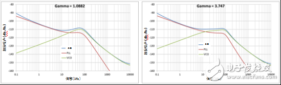
Figure 2: Phase noise vs gamma value is 1.0882 (a); phase noise vs gamma value is 3.747 (b)
Figure 3 shows the maximum gamma value of the maximum loop bandwidth vs achievable under the second-order loop filter. The phase detector frequency and charge pump current remain the same.
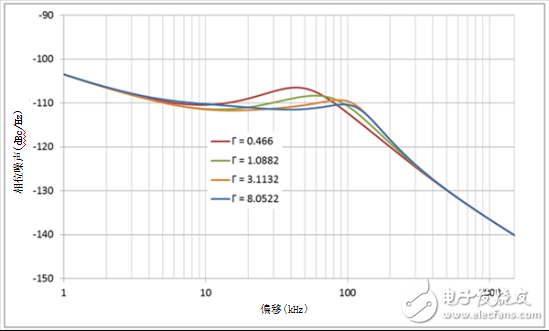
Figure 3: Loop Bandwidth vs Gamma
If the design goal is 100kHz loop bandwidth, 45 degree phase margin, when the gamma value is limited to 1, you can only get a loop bandwidth of up to 79kHz. However, if you can accept higher gamma values, such as gamma values ​​equal to 8, you can achieve your design goals. At this time, the loop bandwidth is 96.6 kHz and the phase margin is 43.4 degrees.
But the higher gamma value also has its cover: the lock time is longer. Figure 4 shows the lock time for a 200MHz frequency jump at different gamma values; the loop bandwidth and phase margin remain the same. When the gamma value and loop bandwidth are 1 and 3.7, respectively, and the stability tolerance is within ±100 Hz, the analog lock time values ​​are 46.5 μs and 118 μs, respectively.
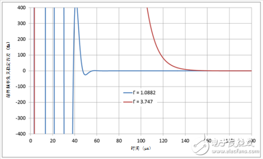
Figure 4: Lock time vs gamma
Use CasesAs long as the gamma optimization parameters are not limited to 1, you are free to develop your PLL ring. For example, if the goal is to achieve a minimum time base error, you typically need to set the loop bandwidth and phase margin to a higher value. If the gamma value is equal to 1, you may not get the desired high loop bandwidth value because the peak of the phase margin response is consistent with the loop bandwidth. In this case, you can sacrifice the lock time by setting a gamma value greater than one. This way, you get a higher loop bandwidth value.
Learn how to quickly calculate gamma and PLL values ​​using the PLLaTInumTM simulation tool. Select "Advanced" in the "Function Level" check box to open the gamma optimization parameter option.
other information· Download the LMX2592 data sheet.
· Learn more about PLL design through the PLL Performance Simulation and Design Manual."
· Understand the following design tools:
· Clock and Synthesizer (TICS) programming software.
· Register programming with CodeLoader software.
WARNING!
Do not plug two or more meters together!
IMPORTANT
Don't plug in an appliance where the load exceeds 16 Amp. Always ensure the plug of any appliance is fully inserted into the meter outlet. If cleaning of the meter is required, remove from mains power and wipe meter with a dry cloth.
KEYBOARD DEFINITION
1). SET: Set price with button UP.
2). MODE: Exchange display state.
3). UP: Set price combined with button SET.
GENERAL FEATURES
1).Display line power.
2).Display and memory accumulative total power quantity.
3).Display and memory total power charge of price.
THE DATA DISPLAY
Press MODE button the data displays as follows:
W →KWh →PRICE →COST/KWH
↑_ _ _ _ _ _ _ _ _ _ _ _ _ _ _ _↓
1). Plug in socket and power on, the meter will display real power.
2). Press MODE button once again and release, the meter will display accumulative KWh.
3). Press MODE button once again and release, the meter will display total power charge.
4). Press MODE button once again and release, the meter will display COST/KWH.
SETTING PRICE OF COST/KWH
1). Press SET button during display COST/KWH,the first digital COST/KWH flash, press UP button to set it.
2). Press SET button once again and release, the second digital COST/KWH flash, press UP button to set it.
3). Press SET button once again and release, the third COST/KWH flash, press UP button to set it.
4). Press SET button once again and release, the fourth COST/KWH flash, press UP button to set it.
5). Press SET button once again and release, the radix point COST/KWH flash, press UP button to set it.
DATA CLEAR
Press and hold MODE button for 5 seconds will clear KWH,PRICE and COST/KWH data.
Power Meter Plug Energy Monitor,Backlight Power Metering Socket,Blue Backlight Power Meter Socket,Multi-functional Backlight Power Meter Socket
NINGBO COWELL ELECTRONICS & TECHNOLOGY CO., LTD , https://www.cowellsockets.com