Abstract: This paper introduces the working principle of closed-loop Hall current sensor and its application in ground vehicle power supply system. It realizes the isolation measurement and control of the output current of vehicle power supply system and solves the current limit of high-power generation system of ground vehicles. Protection issues.
This article refers to the address: http://
Key words: closed loop; Hall current sensor; vehicle power supply; application
 
1 Introduction
The detection and control of the output current of the ground vehicle power system (hereinafter referred to as the power system) is directly related to the stability and reliability of the power system operation, and affects the running condition of the vehicle and the operability of the vehicle. Due to the complicated use conditions of the vehicle, the load of the vehicle power supply changes greatly, and the output power of the power supply will also change greatly. If the output current of the power supply is not limited, the power supply will be heated due to overload, affecting its power. Output, in severe cases, will cause permanent power failure.
The application of the closed-loop Hall current sensor (hereinafter referred to as the sensor) in the vehicle power supply system realizes the isolated measurement of the output current of the power supply system, and controls the output current of the power supply system through feedback. When the output current of the power supply is close to the designed power output of the power system, the power output current will not increase, which limits the output power of the power system and protects the power system from damage due to changes in the power load.
2 How the closed-loop Hall sensor works
Since the discovery of the Hall effect by American physicist Edwin Herbert Hall in 1879, Hall technology has been increasingly used in various fields of industrial control. With the development of component process technology, the performance of Hall current and voltage sensors developed by Hall device applications has also been greatly improved, especially the successful development of closed-loop Hall current and voltage sensors, which greatly expanded the technology. Application area.
2.1 Hall effect and Hall device
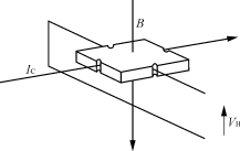
The Hall effect is the theoretical basis for the application of Hall technology. When a semiconductor wafer with a small current is placed in a magnetic field (see Figure 1), the carriers in the semiconductor are deflected by the Lorentz force, making the semiconductor two The potential difference is generated on the side, and the potential difference is the Hall voltage V H , and V H is proportional to the magnetic induction intensity B and the control current I C , and is theoretically estimated to have a relationship of the formula (1).
V H =( R H / d )× B × I C (1)
Where: B is the magnetic induction strength;
I C is the control current;
R H is a Hall coefficient;
d is the thickness of the semiconductor.
In equation (1), if the control current I C is kept constant, under certain conditions, the magnitude of the magnetic induction can be derived by measuring the Hall voltage, thereby establishing a relationship between the magnetic field and the voltage signal. According to this relationship, a semiconductor device for measuring a magnetic field, that is, a Hall device, has been developed.

Figure 1 Hall effect principle
2.2 How the closed-loop Hall current sensor works
The closed-loop Hall current sensor is a modular product that uses a Hall device as a core sensitive component to isolate the detection current. Its working principle is Hall magnetic balance (or Hall magnetic compensation type, Hall zero magnetic formula). . It is well known that when a current flows through a wire, a magnetic field is generated around the wire. The magnitude of the magnetic field is proportional to the amount of current flowing through the wire. This magnetic field can be concentrated by a soft magnetic material and then detected by a Hall device. Since the change of the magnetic field has a good linear relationship with the output voltage signal of the Hall device, the output signal measured by the Hall device can directly reflect the current in the wire, that is,
I ∠B ∠V H (2)
Where: I is the current through the wire;
B is the magnetic induction intensity generated after the wire is passed through.
When the appropriate scale factor is selected, the above relationship can be expressed as an equation.
For the processing of the Hall output voltage signal V H , many kinds of circuits have been designed, but generally can be divided into two categories, one is open-loop (or direct-measurement, direct-check) Hall current sensor; One type is a closed loop (or zero magnetic, magnetic balance) Hall current sensor.
For the circuit form of the Hall sensor, the most easily thought is to directly amplify the output voltage of the Hall device with an operational amplifier to obtain the required signal voltage, thereby calibrating the current measured by the voltage value. This form of Hall sensor is commonly referred to as an open-loop Hall current sensor. The advantage of the open-loop Hall sensor is that the circuit form is simple and the cost is relatively low; its disadvantage is that its accuracy, linearity is poor, response time is slow, and temperature drift is large. In order to overcome the shortcomings of open-loop sensors, closed-loop Hall current sensors appeared in foreign countries in the late 1980s. In 1989, the introduction of foreign technology in Beijing 701 factory took the lead in the development and production of closed-loop Hall current sensors in China. After more than ten years of hard work, this kind of sensor has gradually been understood and applied by users in China.
The closed-loop Hall current sensor works by magnetic balance (Fig. 2), that is, the magnetic field generated by the primary current ( I N ) is compensated by the magnetic field generated by the current ( I M ) of a secondary coil. The Hall device is always in the working state of detecting zero flux. When the magnetic field generated by the primary secondary compensation current reaches equilibrium in the magnetic core,
N 1 × I N = N 2 × I M (3)
Where: N 1 is the number of turns of the primary coil;
N 2 is the number of turns of the secondary coil.
It can be seen from equation (3) that when the primary and secondary coil turns of the sensor are known, by measuring the magnitude of the secondary compensation current I M , the value of the primary current I N can be calculated, thereby realizing the original Isolated measurement of side current.

Figure 2 How the closed-loop Hall current sensor works
3 main performance of closed-loop Hall current sensor
The closed-loop Hall current sensor is a high-tech modular product that has emerged in the past 10 years. Its performance is much better than that of the open-loop Hall current sensor. It also has many advantages compared with the current current measurement method of the current shunt or transformer. The closed-loop Hall current sensor has the following main features:
1) It is possible to measure arbitrary waveform currents simultaneously, such as: DC, AC, pulse current;
2) The secondary side measurement current is completely electrically isolated from the measured current on the primary side, and the insulation voltage is generally 2kV to 12kV;
3) The current measurement range is wide, and the rated current is 1mA~50kA;
4) tracking speed d i /d t >50A/μs;
5) Linearity is better than 0.1% I N ;
6) response time <1μs;
7) Frequency response 0 to 100 kHz.
4 sensor application in vehicle power system
The closed-loop Hall current sensor has a wide range of applications and has been successfully applied to industrial products such as inverter welding machines, power generation and transmission and transformation equipment, electric drives, and CNC machine tools. Table 1 shows the application of this type of sensor by taking the CHB-300S Hall current sensor with a rated current of 300A as an example.
Table 1 Main performance parameters of CHB-300S Hall sensor
| symbol | name | parameter |
|---|---|---|
|   | model | CHB-300S/SP1 |
| I N | Rated current | 300A (RMS) |
| I P | Measuring range | 0~500A |
| I M | Output current | 150mA corresponds to the original side 300A |
| X | Accuracy ( T a =25°C) | ±0.5% of I N |
| K N | Debbie | 1:2000 |
| L | Linearity | <0.1% |
|   | Di/dt | >50A/s |
| I off | Offset current | ±0.3mA (typical) |
| t r | Response time | 1μs |
| V c | voltage | +20 to 30V (±5%) |
| I C | Power consumption | 28mA+ I M |
| t a | Operating temperature | -40°C~85°C |
| t s | Storage temperature | -55 ° C ~ 100 ° C |
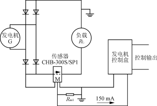
An independent high-power generation system is equipped on a certain type of ground vehicle. The CHB-300S closed-loop Hall current sensor is selected as the system current detection component. The output signal of the sensor is processed and the limit is set. The flow operating point ensures that the output power of the power generation system is not higher than the rated power of the generator. The application of the closed-loop Hall current sensor CHB-300S achieves the above-mentioned application objectives. As shown in Figure 3, the generator G output positive-end busbar passes through the primary current perforation of CHB-300S/SP1, and the generator CHB-300S/SP1 detects the generator output current, the sensor output I M and the generator control. The box is connected, and the output control point of the generator is set by the generator control box. According to this signal, the output current of the generator is limited to prevent the generator from malfunctioning or being damaged due to excessive output power, thereby ensuring the normal power generation system. jobs.

Figure 3 Application of CHB-300S sensor
5 Conclusion
The sensor can meet the technical requirements for current detection of the vehicle power generation system. It has been applied in the power generation system of multiple sets of ground vehicles, and has been tested in accordance with relevant standards. The test results have been affirmed by experts.
-
A Battery Holder is one or more compartments or chambers for holding a battery. For dry cells, the holder must also make electrical contact with the battery terminals. For wet cells, cables are often connected to the battery terminals, as is found in automobiles or emergency lighting equipment. Where the battery is expected to last over the life of the product, no holder is necessary, and a tab welded to the battery terminals can be directly soldered to a printed circuit board. A good choice for you!
Features:
- High Quality Plastic Holder.
- Small size, easy to carry.
- Battery type: Case Holder for 3 x AA Battery. 4.5v
- AA Battery Holder Case with wire leads for soldering / connecting.
- Keep your batteries organized and protected.
Battery Holder
Battery Holder,Waterproof Battery Holder,Christmas Lights Battery Holder,Halloween Lights Waterproof Battery Holder
Dongguan Xingyong Indusrtial Co,Ltd , http://www.xingyongled.com