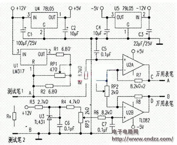
In actual work, in order to analyze the circuit principle, when drawing the electrical schematic according to the physical object, it is often necessary to measure the actual resistance of the small resistance value, such as the constant copper resistance (usually milliohms) used to detect the load current in the high-end switching power supply. Level), high-power small resistance resistor for overcurrent protection (some reach below 0.1Ω), feedback resistor in series with current amplifier tube (E or s pole) in high power amplifier circuit (generally zero ohms) . Since the minimum range of electrical blocking of a conventional digital multimeter is 200 Ω, it is often impossible to accurately measure the specific resistance of these resistors, and it is difficult to determine the consistency of these resistors, which is often difficult. To this end, try to make the auxiliary circuit shown in Figure 1, combined with the DC low voltage block (200mV, 2V, 20V) of the multimeter to achieve accurate measurement of small resistance.
Working principle: a constant current source is used to add a certain current to the measured resistance RX, and then the voltage across Rx is measured by a multimeter. The measured voltage value is divided by the constant current flowing through the measured resistance Rx to obtain the measured resistance. Resistance. Theoretically, the larger the current flowing through the resistance to be tested, the easier it is to accurately measure the resistance of the small resistance resistor Rx, but the current is too large, which will cause severe heat generation of the constant current source, affecting the stability of the current, resulting in the measured resistance. The value is not accurate; the second is that the small power resistor does not allow excessive current to flow. For this purpose, the circuit uses LM317 (U1) and resistors R1, R2 and potentiometer RP1 together to form a simple 100mA constant current source. 
Multimeter low voltage file to measure the actual data of different small resistance resistors
GPS /Glonass/Beidou/Galileo Antenna
1. According to the polarization mode, GPS Antenna can be divided into vertical polarization and circular polarization. With current technology, vertical polarization is not as effective as circular polarization. Therefore, GPS antennas will be circularly polarized except in special cases. 2. GPS antenna is divided into internal antenna and external antenna in the way of placement. The location of the antenna is also important. At this time, the antenna is basically isolated from the interior of the whole machine. EMI is almost not affected. The satellite reception effect is very good. Now, with the trend toward miniaturization, GPS antennas are mostly built in. In this case, the antenna must be higher than all metal components, and the shell must be electroplated and well grounded, away from EMI interference sources, such as CPU, SDRAM, SD card, crystal oscillator, and DC/DC. The use of GPS in cars will become more common. And the car casing, especially the car explosion-proof film can seriously block the GPS signal. An external antenna with magnets, which can be attached to the roof, is essential for onboard GPS. GPS antenna structure
GPS Antenna ,GPS Antenna for Car ,GPS Antenna SMA,GPS Antenna Fakra, Inside GPS Antenna
Yetnorson Antenna Co., Ltd. , https://www.xhlantenna.com