The measures that normally limit the short-circuit current can be considered in terms of power grid structure, system operation mode, and equipment. Although the replacement of circuit breakers and related electrical equipment is a solution, it has the following problems:
1 replacement equipment investment is huge;
2 During the replacement of the equipment, the reliability of the grid system is greatly reduced;
3 Currently, equipment that meets the capacity requirements may not meet the short-circuit current level in the near future. Therefore, quickly limiting faults and large currents has become an extremely urgent problem for current power systems.
Among the various fault current limiters currently developed, the "solid-state current limiter" using power electronic switches and the superconducting current limiter using superconducting technology are two main development lines, both of which have various forms of research results. Based on the exploration of the current limiter and the previous research on the current limiting circuit breaker, the Center for Superconductivity Research and Development of Huazhong University of Science and Technology proposed a design scheme of a parallel inductor superconducting current limiter. The flow device combines power electronic devices, modern control technology and superconducting materials, and can flexibly and quickly perform current limiting, and has the characteristics that the fault current level can be controlled and the superconductor does not lose over during the action.
This paper introduces the structure and principle of the parallel inductor superconducting current limiting circuit breaker, and carries out MATLAB/Simulink simulation. The simulation results are consistent with the theoretical analysis. This is important for the next step to develop the current limiter in the actual power system. Guiding significance.
Main circuit and principleStructure and principle
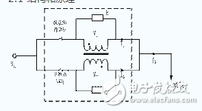
Figure 1 Schematic diagram of shunt inductor fault current limiter
The schematic diagram of the shunt inductor current limiting circuit breaker is shown in Figure 1. It consists of two superconducting coils connected by different names, protective resistors R1 and R2 connected in parallel with the coil, and auxiliary breaker S1 and main breaker S2. . L1 and L2 are the self-inductances of the coils W1 and W2, respectively, M is the mutual inductance between them, Zs is the line impedance, and Sload is the circuit load.
In the normal state, the circuit breakers S1 and S2 are in a closed state, the two coils are in a superconducting state, and the coupling coefficient is 1. The coils W1 and W2 share the line current (Is=I1+I2), and the equivalent structure of the parallel inductor current limiting circuit breaker is shown in Fig. 2. The equivalent impedance of a non-inductively coupled shunt inductor is:
![]() (1)
(1)
The inductor is in a non-inductive coupling state, so the equivalent impedance presented is small, almost 0 (Zcoil ≈ 0), the voltage drop across the inductor is also small, and the entire device is in a low loss standby state.
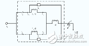
Figure 2 equivalent circuit of parallel inductor fault current limiter
Assume that the coupling coefficient and the ratio of the parallel inductor are defined as ![]() with
with ![]() , the impedance can be expressed as
, the impedance can be expressed as ![]() . When k is infinitely close to 1, Zcoil is almost zero, and the two protection resistors are considered to be "short-circuited".
. When k is infinitely close to 1, Zcoil is almost zero, and the two protection resistors are considered to be "short-circuited".
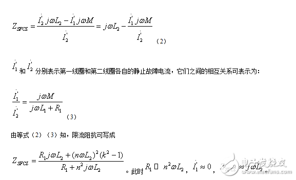
When the system has a short-circuit fault, the system current Is increases sharply. Before the auxiliary breaker S1 operates, the first coil W1 and the second coil W2, which are not inductively coupled, still share the fault current, but the shunt of the shunt inductor reduces the auxiliary trip. The breaking capacity of the device S1 improves its breaking capacity. After the auxiliary circuit breaker S1 is operated, the first winding W1 of the parallel inductor is broken, the parallel inductance is decoupled, the impedance is greatly increased, and the opening of the main circuit breaker S2 is reduced. The breaking capacity increases the breaking capacity, thus ensuring effective interruption of the fault current. The current limiting impedance of the shunt inductor current limiting circuit breaker triggers to limit the fault current, which can be expressed as:
The roles of resistors R1 and R2 are to protect the first coil and the second coil. When S1 is disconnected, the induced current is suddenly interrupted, causing overvoltage to damage the two coils. After R1 is turned on, if the voltage at both ends exceeds its threshold, R1 will be converted to low impedance. Then, L1 and R2 form a continuous loop, and the switching overvoltage will disappear. As the overvoltage disappears, R1 will transition to a high impedance state. When S2 is disconnected, the fault is eliminated and R2 will play the same role.
Parameter design
From the occurrence of the fault to the disconnection of the auxiliary breaker S1, the first coil and the second coil share the fault current. The relationship between the breaking current Icb of S1 and the fault current Isf can be expressed as:
![]() (4)
(4)
From the expressions of k and n, the proportional relationship between Icb and Isf can be rewritten as ![]() . Therefore, adjusting the values ​​of k and n can change Icb, and the breaking capacity of S1 can be flexibly designed. The effect of changing the values ​​of n and k on the ratio of Icb to Isf is shown in FIG. It is known from the figure that the ratio will gradually decrease as n increases. When n=1, the ratio is 0.5 and remains unchanged, ie changing the value of k has no effect on it. Assuming n>1, the ratio will increase as the value of k increases.
. Therefore, adjusting the values ​​of k and n can change Icb, and the breaking capacity of S1 can be flexibly designed. The effect of changing the values ​​of n and k on the ratio of Icb to Isf is shown in FIG. It is known from the figure that the ratio will gradually decrease as n increases. When n=1, the ratio is 0.5 and remains unchanged, ie changing the value of k has no effect on it. Assuming n>1, the ratio will increase as the value of k increases.
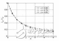
Figure 3 shows the effect of changing the ratio of the ratio n and the coupling coefficient k on the ratio of Icb to Isf.
As shown in Fig. 4, the influence of changing the values ​​of k and n on the impedance of the coupled coil has also been studied. It can be seen that the impedance ZSFCL will increase as the value of n increases. Assuming k = 0.98, although the increase in impedance is not as pronounced as the other two curves, the effect of increasing n on the non-inductive coupling characteristics still needs to be considered.
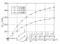
Figure 4 Effect of changing the ratio of the ratio n and the coupling coefficient k on the impedance of the coupled coil ZSFCL
The material used for the parallel coupling coil of the novel non-inductively coupled shunt inductor current limiting circuit breaker is superconducting material, and its main circuit breaker or auxiliary circuit breaker is a power electronic switch or a PWM converter. It has three main features: (1) with non-inductive coupling characteristics; (2) with flexible switch breaking capacity control design; (3) with a combination of main circuit breaker and fault current limiter. Before the current-limiting impedance is triggered, the current through the main circuit breaker is much smaller than the fault current. In the case of n=1, the ratio of the changed k-value is kept at about 0.5. Therefore, compared with other superconducting fault current limiters with only the main circuit breaker series, this new non-inductively coupled shunt inductor fault current limiting circuit breaker can reduce the burden of the main circuit breaker in the initial time of fault occurrence, in addition, The fault currents of the two paths pass, reducing the possibility of damage to the superconducting components. Under the current limiting operation of this current limiter, the fault current will be suppressed from being disconnected by the main circuit breaker at a certain current. It is important in power systems where the short circuit current is larger than the available interrupt circuit breakers.
Simulation analysis
In order to better observe the shunting and current limiting effects, the breaking time of the auxiliary circuit breaker S1 and the main circuit breaker S2 has a certain delay compared with the actual one. Before the fault, the system is in normal operation state. When t=0.026s, the system has a ground short circuit fault at the load end. When t=0.076s, the auxiliary circuit breaker S1 is opened. When t=0.116s, the main circuit breaker S2 is broken.
As shown in FIG. 6 , the voltage drops Uw1 and Uw2 across the first coil W1 and the second coil W2 of the parallel inductor. As can be seen from the figure, before the start of the auxiliary breaker S1, since the parallel inductor is in a non-inductive coupling state, both ends thereof The voltage drop is almost zero, so the loss of the device during normal operation of the system is very low. After the auxiliary circuit breaker S1 is opened, the parallel inductance is decoupled, the impedance is increased, and the second coil W2 becomes the main impedance of the system, so the voltage drop on the inductance is close to the system reactance. In the figure, Uw1 and Uw2 are reversed because the parallel terminals of the parallel inductors are connected.
As shown in Fig. 7, the thin solid line indicates the system current Is, and the thick broken line indicates the auxiliary breaker current I1. When the system is in normal operation, the current peak value is 1.6KA. During the short circuit, the instantaneous peak value of the fault current reaches 13.9KA (≈9IN, IN is the rated current of the line). If only one circuit breaker is used to break the short-circuit current, the open circuit The starting capacity of the device needs at least 14KA, and it can be seen from the figure that due to the shunting effect of the shunt inductor, the current flowing through the auxiliary circuit breaker S1 is only half of the short-circuit current of the system, and the breaking capacity of the fault circuit breaker can be reduced by half, and its breaking capacity. Significantly improved.
As shown in Fig. 8, the thin solid line indicates the system current Is, and the thick broken line indicates the main breaker current I2. Before the auxiliary circuit breaker S1 is disconnected and the parallel inductor is decoupled, the shunt inductor acts as a shunt (Is=I1+I2). After the auxiliary breaker S1 is opened and the parallel inductor is decoupled (t)0.08s), the system is faulty. The current is completely borne by the main circuit breaker S2 (Is=I2), but due to the decoupling of the shunt inductance, the impedance of the device is greatly increased, and the current limiting state is effectively reduced. The peak value is only 3.6KA (≈2.3IN). Therefore, the breaking capacity of the main circuit breaker S2 can be greatly reduced, and its breaking capacity is significantly improved, so that the fault current can be completely cut off effectively, achieving a significant current limiting effect.

Figure 6 Voltage UW1 and UW2 across the shunt inductor
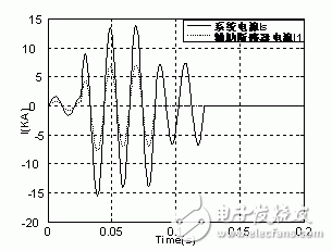
Figure 7 Auxiliary circuit breaker current I1 and system current IS of a parallel inductor current limiting circuit breaker
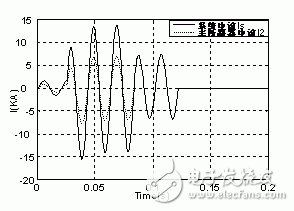
Figure 8 Main circuit breaker current I2 and system current IS of the parallel inductor current limiting circuit breaker
in conclusionAs a new type of large-capacity short-circuit protection device, the shunt inductor fault current limiting circuit breaker proposed in this paper overcomes the shortcomings of the existing circuit breaker breaking capacity, and uses the shunt of the non-inductive coupling shunt inductor to reduce the opening of the auxiliary circuit breaker. The capacity is broken, and the current limit after the decoupling of the parallel inductor is used to reduce the breaking capacity of the main circuit breaker, thereby improving the breaking capacity of the circuit breaker, so that the short-circuit current of the large capacity can be quickly cut off.
The material of the first coil and the second coil connected in parallel with the parallel inductor current limiting circuit breaker is superconducting material, and the protection resistor connected in parallel adopts an adjustable resistor, and the main circuit breaker or the auxiliary circuit breaker is a power electronic switch or PWM communication. Device. For the parallel inductor structure proposed in this paper, it is only in the theoretical analysis and simulation stage. The simulation results are ideal. The problem of dead zone in PWM modulation is not considered. The waveform analysis must be related to the actual waveform. A certain gap. When IGBT is used as the switching device, many specific problems such as system protection problems, startup problems, etc. are not considered, so there is a need for further improvement in subsequent work.
The SFCL involved in this thesis has the characteristics of simple design, low device loss, low operating cost and good current limiting effect. It has broad application prospects in power systems. But to be truly applied, it is necessary to conduct in-depth and meticulous research in order to be better applied to reality. In addition, this article only studies some aspects of FCL. There are still many problems or problems related to FCL in the power system. In the future research on FCL, these topics will become the focus and hotspot. I believe that as more professionals join the research FCL, FCL can be applied to the grid as soon as possible, becoming a backbone technology to improve the security and stability of the power system.
Therefore, the short-circuit current limiter proposed in this paper has great practical value and has a broad application background in the power system.
Battery Holders
Battery Holders
ATKCONN ELECTRONICS CO., LTD , https://www.atkconn.com