Let me talk about how to achieve current sharing. In fact, why the module does not flow evenly is also very simple, that is, the output voltage is inconsistent. Someone may ask, I will adjust the voltage directly and in parallel. If you can guarantee that all module output voltages are exactly the same and the module's impedance characteristics are exactly the same, then direct parallel should be no problem (not tried, not sure) but we can adjust all module voltages exactly and with Is the change in load and the change in the output voltage of the module the same? If you have a method, please give pointers, but in most cases, this situation is not possible. So how do we achieve current sharing? Simply put, it is through the external current sharing circuit that the module output voltage is consistent, the current is large, the voltage is turned down, the voltage is small, and the voltage is turned up, the current sharing can be realized. Is it very simple?
Output impedance methodLet me talk about the first current sharing method, the output impedance method, and the droop method:

Load impedance method can be simply understood as follows, for the module, the larger the output current, the lower the module output voltage, so that the two modules are connected in parallel, the module with the original output voltage is high, the output of the module is increased due to the increase of the output current. When the voltage is reduced, naturally no more current can be output, and the current is provided by the remaining modules. The specific circuit can be realized by the above circuit. The preamplifier circuit amplifies the output current signal, and then superimposes it with the feedback signal to feed the voltage loop. As the current increases, the output voltage can be reduced. Don't stack the wrong ones. If you stack it to the reference end, the logic will be reversed. The higher the current, the higher the output. I have not tried this current sharing method, because the output voltage changes with the increase of current, and sometimes it may change greatly. It is definitely not suitable for modules with voltage regulation accuracy requirements.
3, master-slave setting method
Master-slave setting method: It is to manually set a main module, all modules use this module as a reference to output current. The following figure shows the working diagram of a master-slave set current sharing method on the Internet.
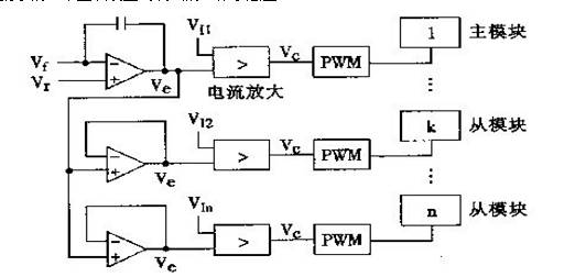
As can be seen from the above figure, in this mode of operation, n units, one of which (master unit) operates in the voltage source (CV) mode, and the remaining n-1 units operate in the current source (CC) mode. It is actually a current-controlled double-loop control consisting of a voltage loop (outer loop) and a current loop (inner loop), or a voltage-controlled current source. The biggest disadvantage of this current sharing method is that the main module is specified in our design process. If there is a problem with the main module during the work, the whole system will be paralyzed.
Average current methodAverage current method: The average current method first needs to obtain an average current, that is, the total load current divided by the total value of the module. The current of each module is compared with the average current. If the module current is greater than the average current, the module output voltage is lowered. On the contrary, the output voltage of the module is increased, so that the output current of each module is consistent. In the average current method, the output current of all modules is connected together through a resistor, and the average value of the output current of all modules can be obtained. This point is called the current sharing bus, as shown in the following figure:
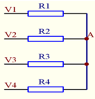
If V1-V4 are the output current values ​​of the four modules respectively, as long as the values ​​of R1-R4 are the same, then the voltage value at point A is (V1+V2+V3+V4)/4, that is, the voltage value on the current sharing bus is The average of the output current of all modules.
With the simple LM324, the average current sharing method can be realized. The specific current sharing circuit diagram and parameters are as follows:
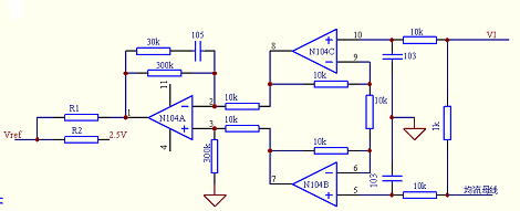
For the circuit in the figure, VI represents the output current signal of this module, which is led out to the current sharing bus through a 1K resistor. The voltage on the current bus is the average value of the output current of all parallel modules. For the schematic diagram above, when the module is separate When working, the current bus is floating, and the op amp input is high impedance. Therefore, the current VI of this module is consistent with the voltage on the current sharing bus, that is, the current of the module does not deviate from the current of the current sharing bus, and the output voltage of the whole circuit ( N1's 1 pin) is 0V. At this time, by setting the value of R1\R2, the output voltage of the module itself can be obtained. When the module is operated in parallel, if the output current of the module is less than the average current, that is, the VI voltage is less than the current sharing bus voltage, then the amplification and subsequent stages are checked. After the amplifier circuit, a voltage value of the VI and the current sharing bus voltage error of 90 times is amplified at the 1st pin, and the output voltage is positive, so that the voltage value of the Vref is raised, thereby increasing the module output voltage and increasing the module output. Current. If the output current of this module is greater than the average current, a low voltage will be output, lowering the reference and lowering the output voltage.
This current sharing mode can not only reduce the output voltage of a module with a large current, but also increase the output voltage of a module with a small current, that is, the voltage is bidirectional.
When the peak is used for the first time, the current sharing mode is adopted. The number of parallel modules is 12, the system output voltage adjustment range is 198-286V, the system voltage regulation accuracy is 0.5%, and the current sharing accuracy is less than 3%.
For the module, the current sharing is basically a part that is free of debugging. The key point is the wiring of the system. The most important point in the system wiring is that the ground of the module output is connected at the nearest position of the module output, that is, all modules. The lower the impedance between the negatives of the output, the better.
Peak current methodThe peak current method means that in all parallel modules, the module automatically elects a master module, and all other module currents are brought closer to the module in an attempt to reach the current of the main module (but never reach it).
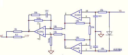
In the average current sharing method, the resistor connected to the current sharing bus is replaced by a diode, which becomes the peak current sharing method. The circuit diagram is as shown in the above figure. Suppose there are N modules connected in parallel, and the voltage corresponding to the module output current is V1. \V2....Vn, it is obvious from the above figure that the current on the busbar will be the voltage Vx of the module with the largest output current of the module (there is a diode drop, even if the average current is equal to four The resistor is replaced by four diodes. It is obvious that the voltage at point A will be the highest voltage minus one diode drop). This module is called the main module. As can be seen from the above circuit diagram, the circuit will adjust the output current of all modules to the corresponding current of the main module, but the voltage difference between the current sharing bus voltage and the main module current is one diode drop. So the output current from the module is always followed by the main module, but not the main module.
Compared with the master-slave setting method, the main module in the current sharing mode is generated by the parallel module itself, so this current sharing mode is also called the democratic current sharing mode. When the main module fails, a module is again elected as the main module in the remaining modules. The system will still work.
The figure below shows a specific circuit of the peak current current sharing mode that has been used. The working principle is basically similar to that of the 3902. The 2.5V reference is used to provide a bias voltage to open the gap between the main module and the slave module. The -2.5V level is for the module to work alone. The current sharing circuit outputs a high level. Thus, in combination with the rear diode, the current sharing circuit does not work.
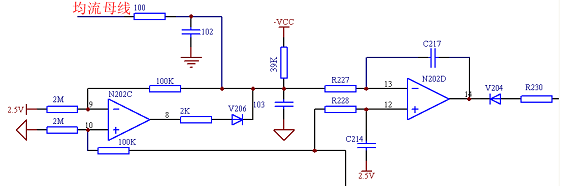
It should be noted that since the bias is provided by 2.5V, the output voltage of the current detecting amplifier circuit should be lower than 2.5V at the rated output current, which is the aforementioned V1.
Pharmaceuticals,2-Methyl- Propanoic Acid Monohydrate Price,2-Methyl- Propanoic Acid Monohydrate Free Sample,Pure 2-Methyl- Propanoic Acid Monohydrate
Zhejiang Wild Wind Pharmaceutical Co., Ltd. , https://www.wild-windchem.com