Instrumentation amplifiers are excellent components for a variety of applications, such as pressure or temperature measurement. Their main functions include signal amplification and impedance matching. In many cases, the instrumentation amplifier has a reference input pin. Increasing the voltage on the reference pin raises the output signal by the same voltage. This makes it easy and precise to adjust the output of the instrumentation amplifier to the input level required by the ADC, allowing the full input range of the ADC to be used while increasing resolution. In the case of a high common mode signal, another advantage is the excellent common mode rejection ratio and high precision.
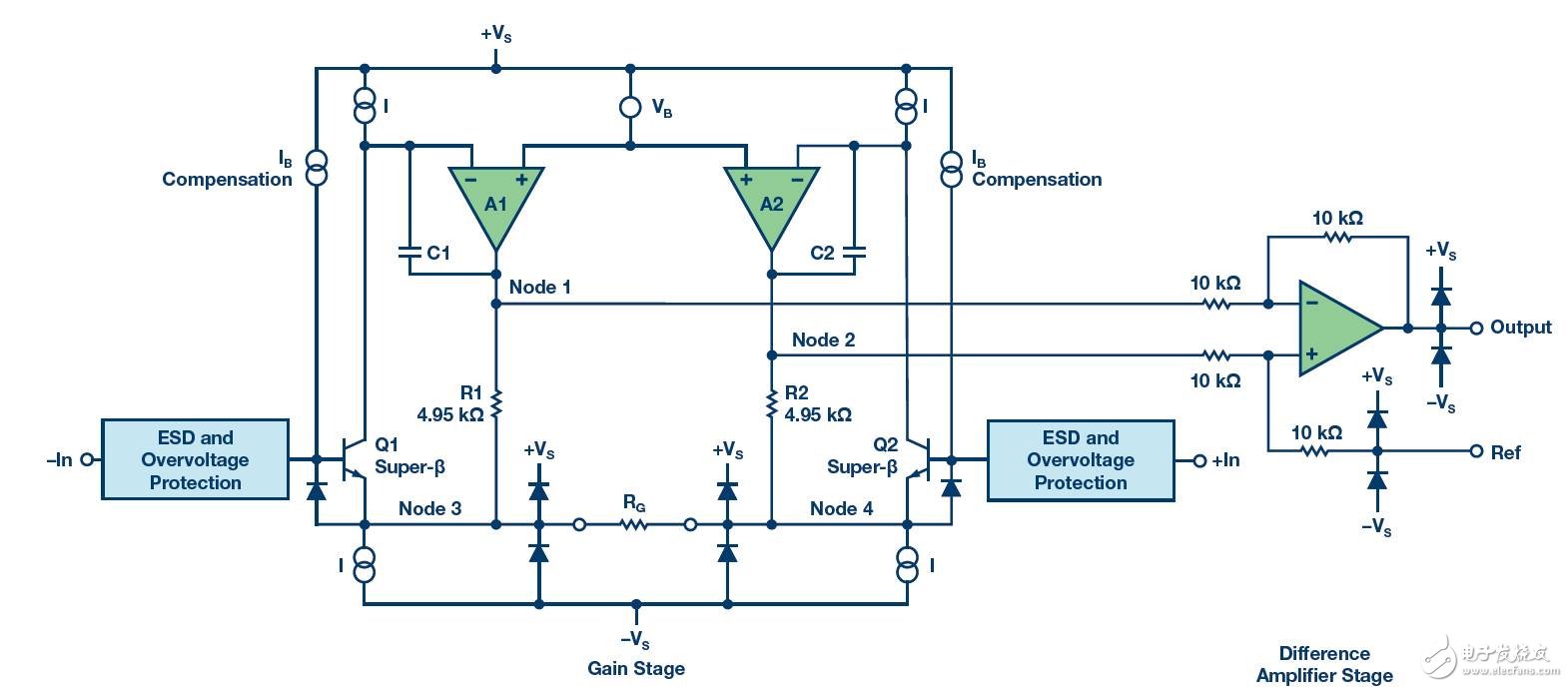
Figure 1 shows the internal schematic of an instrumentation amplifier in a typical 3 op amp design. The AD8421 has universal features for a variety of applications.
When using an instrumentation amplifier, you should be aware that the maximum output voltage depends on the input signal (common mode or differential signal), gain, supply voltage, and possible limitations from internal structures. In the 3 op amp architecture, the first stage amplifier (inverting and non-inverting inputs) amplifies the input signal with a preset gain. The second stage amplifier acts as a subtractor. The output signal consists of subtracting two input signals. The reference voltage is added to the signal that produces the combined output.
After generating this internal analog signal, different factors can now cause internal saturation and possibly reduce the maximum working area.
These factors are as follows:
â–º Input voltage signal is too high for preset gain
â–º The reference voltage is too high for the generated output voltage signal
â–º The power supply voltage is too low
The output voltage and instrumentation amplifier operating area are difficult to calculate due to the maximum input signal, gain, reference voltage, and limitations of the chosen architecture. If you put these factors in a picture, you can get a diamond map, the so-called diamond map. The space of the diamond diagram represents a possible work area. It is not easy to calculate because there are multiple inputs and outputs.
The Instrumentation Amplifier Diamond Map Tool is an online tool developed by Analog Devices that can be used for such calculations. The tool automatically calculates possible configurations for the reference voltage, input signal, supply voltage, and gain of the desired output signal. It graphically displays the possible combinations of parameters for a particular output signal.
This tool contains specifications for all ADI instrumentation amplifiers and is quick and easy to use.

Figure 1. Internal architecture of a typical instrumentation amplifier 
Figure 2. Instrument Diamond Diagram 
Figure 3. Simplified schematic of the instrumentation amplifier 
Figure 4. Recommended Instrumentation Amplifier
Figures 2 through 4 show the graphical user interface of the tool and its diamond map, internal circuitry, and the window corresponding to the recommended tool options.
In the first window (Figure 2), you can enter all the required parameters, calculate the diamond map and visualize it (possible parameters include input signal, gain, supply voltage and reference voltage). For input signals, you can select a common mode signal or a differential signal. In addition, the tool helps determine the limitations of the selected amplifier and distinguishes between input-output and internal limits. The work area can now be estimated. In general, it is recommended not to be too close to the diamond limit when calculating.
The second window of the Instrumentation Amplifier Diamond Diagram tool provides an internal view of the amplifier and displays a detailed schematic (Figure 3). This view shows the technical details and the respective internal voltages. This is very important when you need to check for possible errors in your design. Control modes are also provided to evaluate selected parameters and provide an alternative (Figure 4).
With the instrumentation amplifier diamond map tool, ADI can help you uncover the secrets of diamond maps. The tool provides a simple user interface that is available 24/7 online, allowing you to select and evaluate various instrumentation amplifiers and design more complex schematics at any time.
Here is a quiz:
Analog.com/designtools/en/diamond/
Please select the differential input for the AD8422. The gain is 100, the positive supply voltage is 15 V, and the negative supply voltage is -15 V. The reference voltage is zero. The common mode voltage is 8 V. The VDIFF range is from 100 mV to 148.5 mV. Suppose we use a full temperature range and a 10kΩ load. Please use the diamond map tool and data sheet to explain why this setting is not valid.
Christoph Kämmerer [christoph.] has been a field application engineer at Analog Devices since February 2015. He graduated from the University of Erlangen-Nuremberg in 2014 with a master's degree in physics. After graduating, he worked as a process development intern at Analog Devices in Limerick. After the completion of the trainee program in December 2016, Christoph officially became a field application engineer at Analog Devices, specializing in emerging applications.
LED Tunnel light,Tunnel light of high protection grade
Kindwin Technology (H.K.) Limited , https://www.szktlled.com