The TL431 is the reference voltage in the switching power supply (SMPS) feedback loop. The device combines a reference voltage with an open-collector error amplifier for ease of operation and low cost. Although the TL431 has been widely used in the industry for a long time, some designers still ignore its bias current, which inadvertently reduces the final performance of the product.
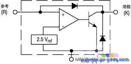
A simplified circuit diagram of the TL431 is shown in Figure 1. The figure includes the reference voltage and error amplifier that drives the NPN transistor. In this closed power system, a portion of the output voltage is always compared to the Vref (reference voltage) of the TL431.

Figure 1 TL431 equivalent circuit diagram

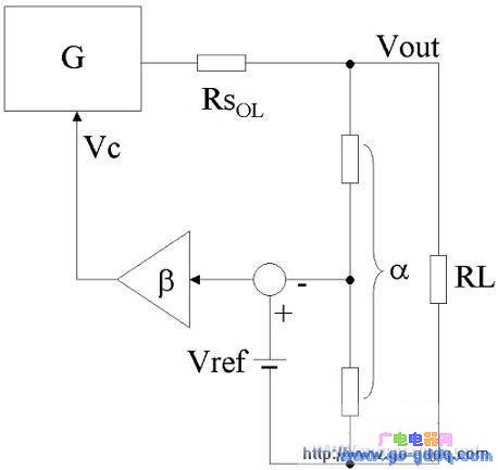
Figure 2 SMPS simplified DC model (regardless of input fluctuations)
The simplified DC model of the converter is shown in Figure 2. Vout and Vref are compared by a resistor divider affected by the transmission rate, and the theoretical value of the output voltage is Vref/α. However, the entire gain chain and various impedances affect the output voltage, as shown in the following equation, where each Greek letter represents a gain and RSOL represents the open-loop output impedance.
Vout=(Vref-α×Vout) ×β×G- RSOL×Vout / RL (1)
Vout= Vref×β×G/(1+α×β×G+ RSOL / RL) (2)
Static error = Vref / α - Vout = Vref × (RSOL + RL) / [α × (RSOL + α × β × G × RL + RL)] (3)
It can be seen from equation (3) that increasing the value of the gain helps to reduce the static error and improve the accuracy of the output voltage. Another important parameter affected by the gain loop is the output impedance. The output impedance of the system can be derived using different calculation methods. Any generator can be simplified to its Thevenin equivalent, a series circuit of a voltage supply Vth (Vout measured at no load, ie RSOL / RL =0 in Equation 2) and an output impedance Rth. When the load resistance RL is the closed-loop output impedance Rth, the output voltage Vout can be reduced to Vth/2, thereby calculating the output impedance Rth, which can also be expressed as RSCL. Let Vth/2 = Vout find RSCL, which is obtained by equation (2):
Vref×β×G/(1+α×β×G)/2=Vref×β×G/(1+α×β×G+ RSOL/Rth) (4)
RSCL = RSOL / (1 + α × β × G) (5)
From equation (5), the following conclusions can be drawn:
If the gain of the DC error amplifier is large and the DC is high, then RsCL is close to zero;
Since the feedback return path is compensated, as the gain decreases as the frequency increases, the RSCL begins to increase. The impedance module increases with increasing frequency, indicating that the impedance is similar to the inductance;
When the gain drops to zero, the system output impedance is the same as the impedance without feedback, both RSOL. At this point, the system works in open loop.
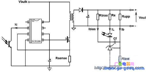
Therefore, in order to reduce static errors and reduce the dynamic output impedance of the converter, most SMPS designers will maintain large DC gain values ​​in their designs. The DC gain here is provided by the TL431 and can be connected using a pure integrator configuration as shown in Figure 3.

Figure 3 Connecting a TL431 using a conventional shunt regulator configuration
Assume that Rbias in Figure 3 does not exist. First calculate the voltage divider network Rupp and Rlow, the bridge current Ib should be greater than the bias current 6.5 A (maximum) of the TL431 reference pin to reduce the Rupp error caused by the bias. For a 12V output voltage, assume Ib = 1 mA. Since the voltage applied by TL431 through Rlow is 2.5V, and the current applied by Rupp is 1mA, it can be calculated that Rlow is 2.5 / 1m = 2.5k?, and Rupp is equal to (12-2.5) / 1m = 9.5k?. A smaller bias current can be further selected to reduce standby energy consumption under no-load conditions. After the bridge current value is determined, the RS can be calculated. The RS must be able to supply enough current to make the optocoupler collector (or feedback pin) less than 1.2V to initiate a skip cycle in no-load operation. In the NCP1200, there is an 8kΩ pull-up resistor between pin 2 and the internal 5V reference. If the feedback current is 475 μA, pull pin 2 to 1.2V (VPIN2=5-475?×8k). Considering that the optocoupler has a 50% current conversion ratio (CTR) under poor conditions, the RS must be less than (Vout-2.5-1V) / 950? <8.94k?, assuming 8.2k?.
In the case of a poor CTR of 150%, it means that the current required in the LED is small. If the 8.2k? resistor is connected in series with the TL431, the following occurs:
1. Light load condition: IFB = 475?A, then IL = 475?/ 1.5 = 316?A
2. Medium load condition: VFB = 2.3V, IFB = 337.5?A, then IL = 337.5? / 1.5=225?A
3. Heavy load condition: VFB = 3V, IFB = 250?A, then IL = 250?/1.5 = 166?A
In this case, the bias current of the TL431 changes not only with the load current but also with the change of the photocoupler CTR. In addition, reducing the RS does not play any role, and the correct feedback voltage at the controller should be adjusted by adjusting the internal current of the LED. The design problem for this case is derived from the TL431 data sheet: a bias current greater than 1 mA must be inserted to benefit from the different specifications of the TL431 gain. If the TL431 is not properly biased, the open-loop gain is reduced, causing the increase and the RSCL to increase.
This problem can be solved by adding a bias resistor Rbias and applying a bias current externally. Since the current is the most lacking, it is necessary to calculate the value of this resistor in the worst case, that is, the heavy load condition and the highest CTR. At this time, IL = 166uA. Therefore, the voltage on the RS is 166? x 8.2k = 1.36V. Assuming a positive voltage drop of 1V for the LED, the cathode voltage is 12 -1.36-1 = 9.64V. It is known that Vout is constant at 12V, obtained by applying 1 mA current through Rbias, Rbias = (12-9.64) / 1m = 2.36k?, or a normalized value obtained with 2.2k?. Therefore, the minimum current applied to the TL431 is 1 mA + 166 uA = 1.16 mA. Under no-load conditions, IL=316 uA and cathode voltage is 12-(8.2k×316)-1 = 8.4V. Therefore, the total bias current flowing through TL431 is (12-8.4)/2.2k= 1.63mA. With the actual feedback current value of 316uA, the total bias current is 1.95mA, which should be within the safe current range.
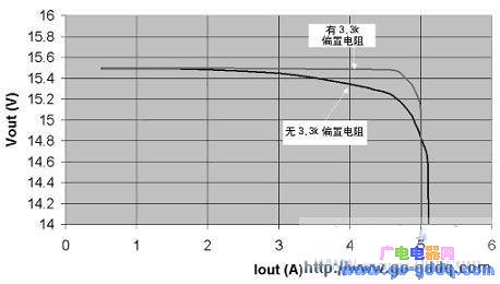
Experiments with bias resistors and no bias resistors were performed on the power supply formed by the NCP1200. The results are shown in Figure 4. When there is no biasing component, the output impedance is measured as 57m?; after the biasing resistor (resistance is 3.3k?), the output impedance is reduced to 4m?.

Figure 4 TL431 performance will be significantly reduced when the bias current is too low
In summary, it is very important to properly bias the TL431 with an external resistor. If you cannot afford the extra 1mA output current budget (because you want to minimize the no-load standby energy consumption), you should use TLV431 (Vref = 1.24V) or NCP100 (Vref = 0.7V) because they only need a minimum of 100?A. Bias current and a smaller breakdown voltage. In addition, the 8.2kΩ series resistor RS is extremely rare because it combines with the collector pull-up resistor of the optocoupler to produce a DC gain. If the resistance value is about 1k or slightly larger than 1k, it is closer to the standard value.
Iget Vape,Disposable Vape Iget Dual,Iget Dual Vape,Iget Xxl Disposable Vape Device
Nanning Nuoxin Technology Co., LTD , https://www.nx-vapes.com