The buzzer is an integrated electronic sounder. This article describes how to use a single-chip microcomputer to drive the buzzer. He is widely used in computer, printer, copier, alarm, telephone and other electronic products for sounding devices.
The buzzer is mainly divided into two types: a piezoelectric buzzer and an electromagnetic buzzer.
The electromagnetic buzzer is composed of an oscillator, an electromagnetic coil, a magnet, a diaphragm, and a casing. After the power is turned on, the audio signal current generated by the oscillator passes through the electromagnetic coil, causing the electromagnetic coil to generate a magnetic field, and the vibrating diaphragm periodically vibrates and sounds under the interaction of the electromagnetic coil and the magnet.
The piezoelectric buzzer is mainly composed of a multivibrator, a piezoelectric buzzer, an impedance matching device, a resonance box, an outer casing and the like. The multivibrator is composed of a transistor or an integrated circuit. When the power is turned on (1.5~15V DC working voltage), the multivibrator starts to oscillate and outputs an audio signal of 1.5 to 2.5 kHz, and the impedance matching device pushes the piezoelectric buzzer. Sounds.
The following is a picture and structure of the electromagnetic buzzer. . .
Electromagnetic buzzer physical map:
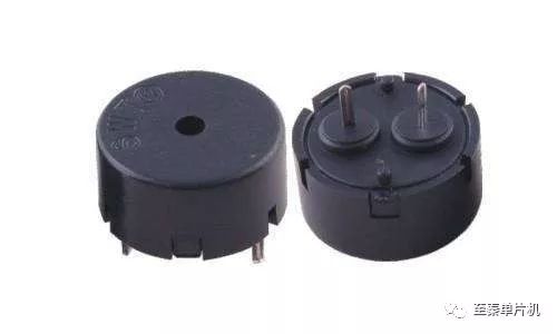
figure 1
Schematic diagram of electromagnetic buzzer:
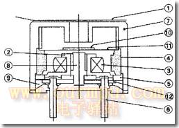
figure 2
The internal structure of the electromagnetic buzzer:
Waterproof sticker
2. Spool
3. Coil
4. Magnet
5. Base
6. Pin
7. Shell
8. Iron core
9. Sealing
10. Small iron pieces
11. Vibration film
12. Board
First, the electromagnetic buzzer drive principle
The buzzer sounding principle is that the current passes through the electromagnetic coil, so that the electromagnetic coil generates a magnetic field to drive the diaphragm to sound. Therefore, a certain current is required to drive it. The current output of the IO pin of the single chip microcomputer is small, and the TTL level of the single chip output is basically The buzzer cannot be driven, so it is necessary to add a current amplification circuit. The S51 enhanced MCU experiment board amplifies the driving buzzer through a triode C8550. The schematic diagram is shown in Figure 3 below:
S51 enhanced single-chip experimental board buzzer drive schematic:
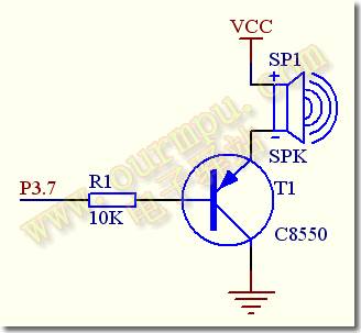
image 3
As shown in the figure, the positive pole of the buzzer is connected to the VCC (+5V) power supply, the negative pole of the buzzer is connected to the emitter E of the triode, and the base B of the triode is passed through the current limiting resistor R1. Foot control, when P3.7 outputs a high level, the transistor T1 is cut off, no current flows through the coil, the buzzer does not sound; when the P3.7 output is low, the triode is turned on, so that the current of the buzzer forms a loop. Make noise. Therefore, we can control the level of P3.7 pin to make the buzzer sound and turn off.
In the program, the frequency of the P3.7 pin output waveform is changed, and the buzzer tone can be adjusted to generate various sounds and tones. In addition, by changing the high and low duty ratio of the P3.7 output level, you can control the sound level of the buzzer, which can be verified by programming experiments.
Second, the buzzer list
Below we give a few simple microcontroller-driven buzzer programming and circuit design columns.
1. Simple buzzer experiment program: This program sends a square wave of audio range in P3.7 to drive the buzzer on the experiment board to emit a beep. The function of DELAY delay subroutine is to make the output The square wave frequency is below 20KHZ within the human ear's hearing ability. Without this delay program, the output frequency will greatly exceed the human ear's hearing ability, and we will not hear the sound. By changing the delay constant, you can change the output frequency and adjust the tone of the buzzer. You can change #228 to other values ​​in the experiment and listen to the changes in the buzzer pitch.
ORG 0000H
AJMP MAIN ; Jump to main program
ORG 0030H
MAIN: CPL P3.7; buzzer drive level is reversed
LCALL DELAY; delay
AJMP MAIN; repeated loop
DELAY: MOV R7, #228; delay subroutine, change the delay constant to change the tone of the buzzer
DE1: DJNZ R7, DE1
RET
END
2. Reversing warning sound test procedure: We know that when various trucks and container trucks are reversing, they will issue a beeping warning sound of reversing, and at the same time, the warning yellow light will also flash simultaneously to remind the person or vehicle behind to pay attention. The experimental routine implements the reversing warning function, and the warning sound is emitted through the buzzer on the experiment board, and the yellow warning light is emitted through the two yellow LEDs on the experimental boards P1.2 and P1.5.
ORG 0000H
AJMP START ; jump to the initialization program
ORG 0033H
START:
MOV SP, #60H ; SP initialization
MOV P3, #0FFH; port initialization
MAIN: ACALL SOUND; buzzer sounds
ACALL YS500M; delay
AJMP MAIN
SOUND:
MOV P1, #11011011B ; Lighting 2 warning yellow LEDs
MOV R2, #200; ringing 200 cycles
SND1: CLR P3.7; output low level T1 is on, buzzer sounds
ACALL YS1ms; delay
SETB P3.7; output high level T1 cut off, buzzer does not ring
ACALL YS1ms; delay
DJNZ R2, SND1
MOV P1, #0FFH ; Turn off the yellow warning light
RET
YS1ms: ;1ms delay subroutine
MOV R0, #2
YL1: MOV R1, #250; changing the value of R0 can change the sound frequency
DJNZ R1, $
DJNZ R0, YL1
RET
YS500M: ;500ms delay subroutine
MOV R0, #6
YL2: MOV R1, #200
YL3: MOV R2, #250
DJNZ R2, $
DJNZ R1, YL3
DJNZ R0, YL2
RET
END
3, "å®å’š" electronic doorbell experiment program: common household electronic doorbell when there is a guest visit, if you press the doorbell button, the room will emit a "beep" sound, this experimental program simulates the pronunciation of the electronic doorbell, when we press the experiment When the K1 button on the board, the buzzer sounds "beep" music, which is a more practical program.
"å®å’š" electronic doorbell experiment ASM source program:
"å®å’š" electronic doorbell C language source program:
ORG 0000H
LJMP START ; jump to the initialization program
ORG 000BH
LJMP PGT0 ; Jump to T0 interrupt service routine
START:
OBUF1 EQU 30H ; initialization procedure
OBUF2 EQU 31H
OBUF3 EQU 32H
OBUF4 EQU 33H
FLAGB BIT 00H
STOPB BIT 01H
K1 BIT P3.2; define button K1 as the doorbell button
MOV TMOD, #02H ; Timer initialization
MOV TH0, #06H
MOV TL0, #06H
SETB ET0; start timer T0
SETB EA; start total interruption
MAIN: ; main program
JB K1, MAIN; detect K1 button
LCALL YS10M; delay debounce
JB K1, MAIN
SETB TR0 ; button is valid
MOV P1, #00H ; lit button indicator
MOV OBUF1, #00H
MOV OBUF2, #00H
MOV OBUF3, #00H
MOV OBUF4, #00H
CLR FLAGB
CLR STOPB
JNB STOPB, $
MOV P1, #0FFH
LJMP MAIN; after the "å®å’š" is finished, return to the re-detect button
YS10M: ;10ms delay subroutine
MOV R6, #20
D1: MOV R7, #248
DJNZ R7, $
DJNZ R6, D1
RET
PGT0: ; Timer T0 interrupt service routine
INC OBUF3; a "beep" sound is heard in the interrupt service routine
MOV A, OBUF3
CJNE A, #100, NEXT
MOV OBUF3, #00H
INC OBUF4
MOV A, OBUF4
CJNE A, #20, NEXT
MOV OBUF4, #00H
JB FLAGB, PGSTP
CPL FLAGB
AJMP NEXT
PGSTP:
SETB STOPB
CLR TR0
LJMP INT0RET
NEXT: JB FLAGB, SOU2
INC OBUF2
MOV A, OBUF2
CJNE A, #03H, INT0RET
MOV OBUF2, #00H
CPL P3.7
LJMP INT0RET
SOU2: INC OBUF1
MOV A, OBUF1
CJNE A, #04H, INT0RET
MOV OBUF1, #00H
CPL P3.7
LJMP INT0RET
INT0RET:
RETI
END
#include
Unsigned char obuf1;
Unsigned char obuf2;
Unsigned int obuf3;
Bit stopb;
Bit flagb;
Void main(void)
{
Unsigned char i,j;
TMOD=0x02; //Timer T0 initialization
TH0=0x06;
TL0=0x06;
ET0=1;
EA=1; //Allow total interruption
While(1)
{
If(P3_2==0) //Detect K1 button
{
P1=0x00;
For(i=10;i>0;i--)
For(j=248;j>0;j--);
If(P3_2==0)
{
Obuf1=0;
Obuf2=0;
Obuf3=0;
Flagb=0;
Stopb=0;
TR0=1; //Start timer T0 and make a “beep†sound
While(stopb==0);
P1=0xff;
}
}
}
}
Void t0(void) interrupt 1 using 0
{
Obuf3++;
If(obuf3==2000)
{
Obuf3=0;
If(flagb==0)
{
Flagb=~flagb;
}
Else
{
Stopb=1;
TR0=0;
}
}
If(flagb==0)
{
Obuf2++;
If(obuf2==3)
{
Obuf2=0;
P3_7=~P3_7;
}
}
Else
{
Obuf1++;
If(obuf1==4)
{
Obuf1=0;
P3_7=~P3_7;
}
}
}
UCOAX manufactures a wide spectrum of wire and cable assemblies, each custom-designed for each individual client. Coaxial cable, at the industrial level, is used for instrumentation, control, RF, and microwave applications. It is also commonly used to connect home video equipment and cable television. These cable assemblies are available both rigid and flexible options, and consist of four layers: a round conducting wire, insulating spacer, cylindrical conducting sheath, and a final insulating layer. For any cable fabrication needs, contact UCOAX.
Customized Cables,Custom Pc Cables,Custom Computer Cables,Custom Network Cables
UCOAX , https://www.jsucoax.com