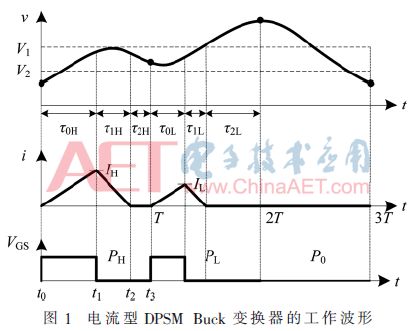
Conventional switching DC-DC converters generally use the Pulse Width Modulation (PWM) technology to achieve closed-loop control of the switching DC-DC converter. As a linear fixed-frequency variable pulse width modulation technology, PWM realizes the control of the output voltage of the switching converter by adjusting the duty cycle technology of the control pulse. At present, the development of PWM modulation technology is relatively mature, and has been widely used in the power electronics industry. As the requirements for power system performance continue to increase, the linear modulation-based PWM modulation technique has always been unsatisfactory in terms of robustness and transient response. The introduction of the nonlinear control method effectively improves the dynamic characteristics of the system and solves the problems in the above linear control technology. This control technology has attracted the attention of researchers at home and abroad.
As a nonlinear control technology, Pulse Skipping Modulation (PSM) technology has been widely used in industry since its introduction. Compared with PWM technology, PSM technology has the advantages of simple circuit design, fast transient response and high efficiency at light load. Literature [11] proposed DPSM technology, which combines PSM technology and Pulse Train (PT) technology. The working principle is to determine the selection of the power pulse of the pulse sequence controller according to the relationship between the output voltage of the switching power supply and the reference voltage, and finally ensure that the output voltage reaches a steady state. However, the voltage type DPSM Buck converter proposed in the literature is controlled by a single voltage loop. This technology is prone to current overshoot when the circuit is started. It is necessary to add a soft start circuit and an overcurrent protection circuit to protect the circuit, thus increasing the circuit. The complexity of the design. In response to the above problems, this paper proposes a current-mode DPSM technology that successfully eliminates current overshoot during circuit startup and maintains all the advantages of voltage-based DPSM technology.
The current-type DPSM technology is a simple switching DC-DC converter control method with unique control mode. At present, there is no relevant theoretical analysis and research report on dynamic modeling. In this paper, the Buck converter is taken as an example. Firstly, the basic working principle of the current-mode DPSM technology is deduced, and the relationship between the output voltage variation and the load resistance is derived. Secondly, the dynamics modeling of the DPSM Buck converter operating in DCM is performed. The load resistance is the bifurcation analysis of the variable. Finally, the correctness of the theoretical analysis of the current-type DPSM technology is verified by PSIM simulation result analysis and experimental circuit fabrication.
Dynamics modeling and pulse combination lawDynamic Analysis of 1 Buck Converter


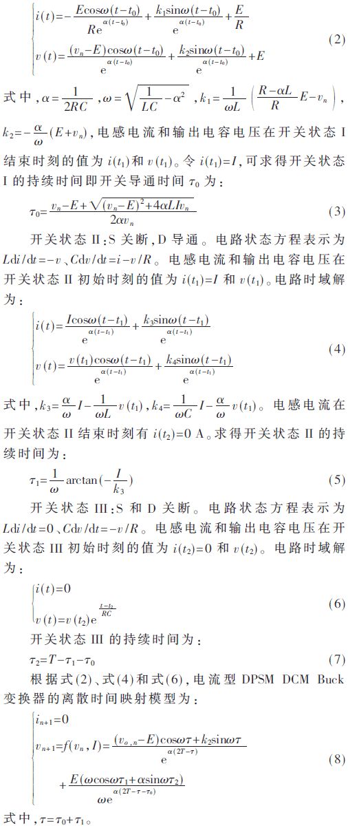
It is assumed that in and vn, in+1 and vn+1 are the sample values ​​of the inductor current i(t) and the output capacitor voltage, that is, the output voltage v(t) at the times of the clocks nT and (n+1)T. According to three different circuit topologies in one switching cycle, the time domain solutions in different states can be obtained.
Switching state I: The switching transistor S is turned on, and the freewheeling diode D is turned off. The circuit state equation is expressed as Ldi/dt=-v+E, Cdv/dt=iv/R, and the time domain solution is:

The discrete time mapping model described by equation (8) is a two-dimensional discrete dynamics system model. Since the current-mode DPSM DCM Buck converter is always zero at the beginning and end of each switching cycle, the model described in equation (8) can be reduced to a one-dimensional discrete-time mapping model, namely:

Substituting the inductor currents IH and IL into equation (9), we can obtain:

2 pulse combination analysis
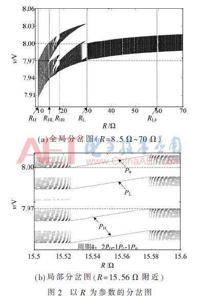
The bifurcation behavior of the output voltage of the current-type DPSM DCM Buck converter can be analyzed by equation (10). The load resistance R is selected as the bifurcation parameter, and the variation range is 8.5 Ω~70 Ω. The result is shown in Fig. 2(a).
When R=RH, the running track of the converter and the boundary B2 have the first boundary collision, and the pulse sequence issued by the controller is changed from a single PH pulse combination to a combination of PH and PL pulses; as the load resistance increases, when When R=RHL, the multi-cycle rail break of the converter collides with the boundary V2, and the first collision bifurcation occurs with the boundary V1. The three trajectories of the converter appear at the same time. The pulse sequence sent is the combination of PH, PL and P0 pulses; as the load resistance R further increases, when R=RL, the multi-period orbit of the converter and the boundary V1 have the last collision and the collision with the boundary V2. After the bifurcation, the pulse sequence emitted by the controller becomes a combination of PL and P0 pulses. In order to clearly observe the bifurcation phenomenon and the pulse combination mode, Fig. 2(b) shows a partial partial map near R = 15.56 Ω.

In Fig. 2(a), V1 and V2 are respectively bounded, and the discrete points below the boundary V2 represent the running trajectory of the output voltage under the action of the power pulse PH, and the discrete points between the boundaries V1 and V2 represent the output of the PL. The running track of the voltage, the discrete points above the boundary V1 represent the running trajectory of the output voltage under the action of P0. When R In order to verify the feasibility of the current-type DPSM controller, the Buck converter controlled by it is used for experimental verification and its test is verified. The circuit model was built using PSIM simulation software, and the current-mode DPSM DCM Buck converter was experimentally studied. Figure 3 shows the time-domain waveforms of v, i, and VGS for the current-mode DPSM DCM Buck converter with R of 11.7 Ω, 22.2 Ω, and 43 Ω in the [10, 70] interval. In Figure 3(a), R=11.7 Ω, the pulse sequence of the controller output is 2PH-1PL; in Figure 3(b), R=22.2 Ω, the pulse sequence combination is 1PH-2PL-1P0; in Figure 3(c) R = 43 Ω, the pulse sequence combination is 2PL-1P0. The inductor currents in Figure 3 are all in DCM. The output voltage ripple of Figure 3(a) is approximately 70 mV; the output voltage ripple of Figure 3(b) is approximately 60 mV; and the output voltage ripple of Figure 3(c) is approximately 35 mV. The experimental results are basically consistent with the circuit simulation results built with PSIM simulation software. In this paper, the current-mode DPSM control technology is proposed. According to its working principle, the dynamics is modeled and the relationship between the output voltage variation and the load resistance is obtained. The PSIM circuit simulation and experimental circuit observation prove the accuracy and feasibility of the theoretical analysis. A power pulse cycle of a current-mode DPSM DCM Buck converter is determined by the number of high- and low-power pulses and cross-cycle pulses and their combination. Analysis knows that when R 
Gaming Earbuds With Mic,Metal Body Earphones,Sport Metal Headphone,Wired Metal Earphone
Guangzhou YISON Electron Technology Co., Limited , https://www.yisonearphone.com