In modern control systems, angle measuring devices are critical components that require high precision, and their measurement accuracy directly affects the performance and accuracy of the entire system. For example, the construction elevator has an angle measuring and controlling mechanism to control the take-off and landing; the rocket launching system has a large number of angle sensors to detect the turret deflection angle in real time, so as to adjust the rocket gun aiming. At present, the existing acceleration sensors are used to realize high-precision angle measurement, and mainly focus on single-axis angle measurement. This article will focus on the hardware and software methods for achieving high-precision angle measurement using the ADXL202 dual-axis acceleration sensor.
1 angle measuring instrument system hardware design
This angle measuring instrument uses STM32F107 as the core chip for data processing. This is a low power, high speed 32-bit processor with a Cortex-M3 core. The angle measuring module uses a high-precision, low-power dual-axis accelerometer ADXL202, which can convert the acceleration signal into a digital square wave signal output, which can be directly connected to the STM32F107, and the current tilt angle can be calculated by a certain algorithm. The display module uses a 12864ZW type 128 & TImes; 64 dot matrix liquid crystal display
2 angle measurement module
The angle measurement module uses the low-cost, low-power, high-precision dual-axis accelerometer ADXL202 from Analog Devices, Inc., with a measurement range of -2g to +2g, which measures both dynamic acceleration and static acceleration. Its operating voltage is 3.0 ~ 5.25 V, the operating current is less than 0.6 mA, the highest frequency can reach 70 MHz, so in terms of power consumption, sensitivity and accuracy, choose ADXL202 as the core chip of the angle measurement module. Figure 2 is a block diagram of its functional structure.
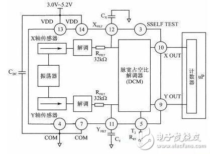
Figure 2 Functional block diagram of the ADXL202
As can be seen from Figure 2, the ADXL202 is a perfect dual-axis acceleration measurement system based on a single integrated circuit. For the X and Y axes, the output loop converts the acceleration signal into a digital signal output with a pulse width duty cycle. These digital signals It can be transferred directly to the STM32F107 without the need for A/D conversion or other additional circuitry.
The ADXL202 consists of an oscillator, X and Y axis sensors, a phase demodulator, and a pulse width duty cycle demodulator. Its function is realized by the square wave of the output amplitude change after the X and Y axis sensors are subjected to the acceleration force. The amplitude of the square wave is proportional to the acceleration. The phase demodulator can correct the output square wave signal and extract the information, and then determine the acceleration direction. The output of the phase demodulator passes through a low-pass filter circuit that sets the bandwidth of the output signal by changing the size of the filter capacitor. The low-pass filtered analog signal enters the DCM and is converted to a pulse width duty cycle signal output.
2.1 Angle measurement module hardware circuit design
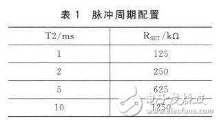
In order to ensure the high precision and stable operation of the ADXL202, it is necessary to configure the signal period and the filter capacitor (determining the bandwidth of the signal) according to the chip technical documentation and actual use.
The output signal of the ADXL202 is a pulse width duty cycle modulated signal, and the duty cycle T1/T2 is proportional to the measured acceleration. At 0g, the output is 50% duty cycle, and the sensitivity is 12.5% ​​of the pulse width duty cycle caused by each g. Refer to the chip's technical documentation to set the DCM period by the resistor RSET:
T2=RSET/125 MΩ(1)
The value of the acceleration component in the X and Y directions can be calculated by:
A(g)=(T1/T2-0.5)/12.5% ​​(2)
Table 1 is the RSET and T2 configuration table provided by the chip's technical documentation. We choose RSET of 125 kΩ and set the period T2 to 1 ms.
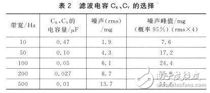
The ADXL202 sets the bandwidth of the ADXL202 through XFILT, YFILT external capacitors CX, CY. This bandwidth determines its measurement accuracy, while the capacitors CX and CY can be aliased and filtered. In order to minimize the error of the pulse width duty cycle, the analog bandwidth should be 1/10 lower than the pulse width duty cycle. Analyze Table 2 provided in the technical documentation, and consider setting T2 to 1 ms, pulse duty cycle. The frequency is 1 kHz. To meet the actual needs and the minimum DCM error, select a filter capacitor of 0.05μF. The analog bandwidth is 100 Hz.
Pin connection specifications: 13, 14 are two voltage input pins VDD, directly connected to the 5 V power supply, while connecting the decoupling capacitor CDC, it is recommended to use 0.1μF; 4, 7 are two ground pins COM, directly grounded 2 pin VTP remains open, not connected to any other pin; 3 pin ST is the self-test input terminal, can check the function of the accelerometer when connected to VDD, usually the pin is open circuit, can also be connected with COM. The pin configuration is shown in Figure 3.
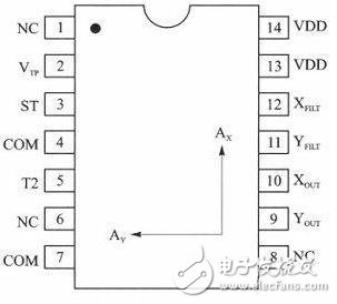
Figure 3 ADXL202 pin configuration
According to the chip's pin configuration diagram and the above various configurations, the hardware circuit of the angle detection module can be designed. The circuit principle is shown in Figure 4. The pulse output terminal is directly connected to the I/O port of the STM32F107.
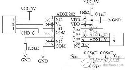
Figure 4 angle acquisition schematic
SHENZHEN CHONDEKUAI TECHNOLOGY CO.LTD , https://www.siheyidz.com