As the demand for global connectivity grows, many satellite communication systems are increasingly adopting the Ka-band. Do you know how much bandwidth the Ka band needs?
Today, let's talk about the bandwidth required for the Ka-band from a number of technical specifications, transceiver architectures, and signal chains for Ka-band satellite communication systems.
[Down down technical specifications from system level analysis]
At a macro level, satellite communication systems need to maintain a certain carrier-to-noise ratio (CNR), which is the result of link budget calculations. Maintaining this CNR guarantees a certain bit error rate (BER). The required CNR depends on various factors such as error correction, information coding, bandwidth, and modulation type. Once the CNR requirements are determined, the specifications for each receiver and transmitter can be decomposed down to the high-level system requirements. In general, the first gain is the gain-system noise temperature (G/T) quality factor of the transceiver and the effective isotropic radiated power (EIRP) of the transmitter.
For the receiver, to get the low-level receiver signal chain specification from G/T, the system designer needs to know the antenna gain and the system noise temperature, which is a function of the antenna pointing and receiver noise temperature, as shown in Equation 1. Based on this, the receiver temperature can be obtained using Equation 2.
  |
The noise figure of the receiver signal chain can then be calculated using Equation 3:
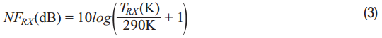 |
Once the receiver noise figure is known, a cascade analysis can be performed to ensure that the signal chain meets the requirements of these necessary specifications and that adjustments are needed. For the receiver, the required EIRP is first determined based on the distance of the receiver (ground to satellite or satellite to ground) and receiver sensitivity. After knowing the EIRP requirements, a compromise between the output power of the transmit signal chain and the antenna gain is required. For high gain antennas, the power consumption and size of the transmitter can be reduced, but at the expense of increased antenna size. EIRP is calculated by Equation 4.
 |
As long as the components used in the signal chain are carefully selected, the output power can be maintained without causing other important parameters to fall, such as interference with other systems' output noise and out-of-band RF energy.
Other important technical specifications for transmitters and receivers include
Instantaneous bandwidth: the spectral bandwidth that the signal chain can digitize at any point in time.
Power processing: The maximum signal power to be processed by the signal chain without causing performance degradation
Phase coherence between channels: For emerging beamforming systems, ensuring predictability of phase between channels simplifies beamforming signal processing and calibration
Spurious performance: Ensure that the receiver and transmitter do not generate RF energy at undesired frequencies to avoid affecting the performance of the system or other systems

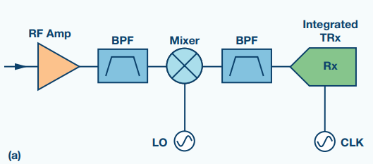
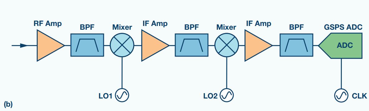
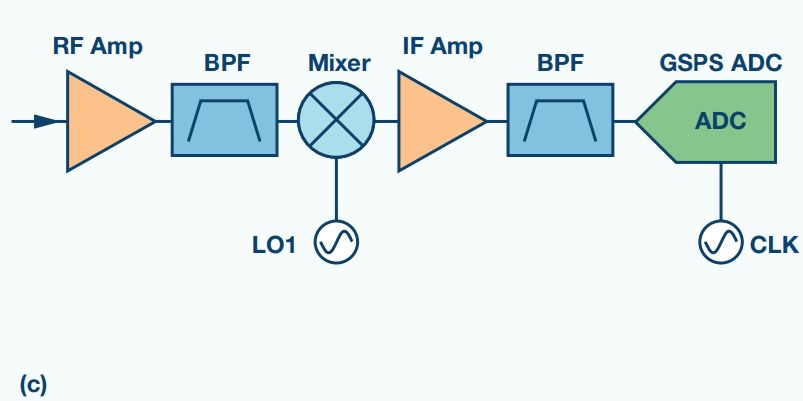
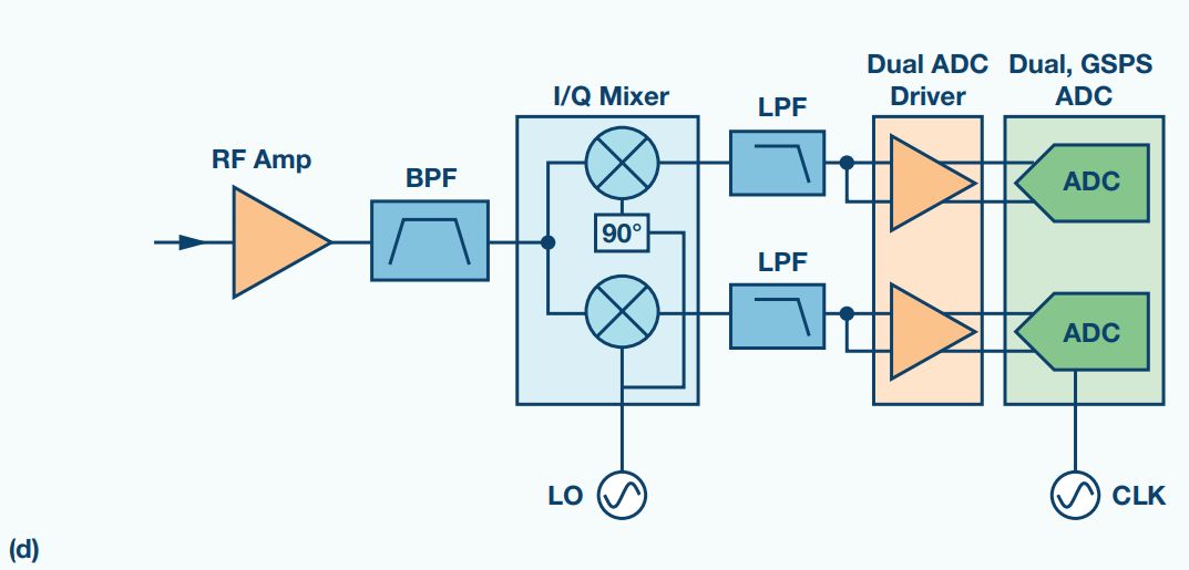
Figure 1. Architecture comparison, (a) high IF (integrated TRx), (b) dual-conversion superheterodyne architecture (with GSPS ADC), (c) single-conversion superheterodyne architecture (with GSPS ADC), (d) direct Frequency conversion (with I/Q mixer).
These and other specifications must be kept in mind during the signal chain design process to ensure that high performance systems are designed to meet the needs of any given application, whether it is a broadband multi-carrier aggregation hub or a single narrowband handheld satellite communication terminal.
[Common Architecture Comparison]
Once you have determined the high-level specifications, you can decide which signal chain architecture to use. One of the key technical specifications listed above and potentially having a significant impact on the architecture is instantaneous bandwidth. This specification affects the receiver's analog-to-digital converter (ADC) and the transmitter's digital-to-analog converter (DAC). In order to achieve high instantaneous bandwidth, the data converter must be sampled at a higher rate, which generally pushes up the power consumption of the entire signal chain, but if it is in terms of unit power consumption (W/GHz), it will reduce power consumption. .
For systems with less than 100 Mhz bandwidth, in many cases it is best to use an infrastructure similar to Figure (a). The architecture combines a standard downconversion stage with an integrated direct conversion transceiver chip. The integrated transceiver enables ultra-high levels of integration, resulting in significant size and power savings.
To achieve a bandwidth of 1.5 Ghz, the classic dual-conversion superheterodyne architecture can be combined with the most advanced ADC technology, as shown in Figure (b). This is a mature, high-performance architecture with an integrated inverter stage for filtering out unwanted spurious signals. According to the received frequency band, the received signal is converted to an intermediate frequency (IF) by a down conversion stage, and then the final intermediate frequency signal is converted into a low frequency signal that the ADC can digitize with another down conversion stage. The lower the intermediate frequency, the higher the ADC performance, but at the cost of increased filtering requirements. In general, due to the increased number of components, this architecture is the largest and most power-efficient architecture among the four options presented in this article.
A similar option is shown in Figure (c), which is a single-stage conversion stage that converts the signal to a high IF and is sampled by the GSPS ADC. This architecture takes advantage of the increased RF bandwidth that the ADC can digitize, with little performance degradation. The latest GSPS ADCs on the market can directly sample RF frequencies up to 9 Ghz. In this option, the IF center is between 4 Ghz and 5 Ghz to achieve the best balance between signal chain filtering requirements and ADC requirements.
The last option is shown in Figure (d). The instantaneous bandwidth increase of this architecture is even larger, but the cost is very complicated and may lead to performance degradation. This is a direct conversion architecture that uses a passive I/Q mixer that outputs two intermediate frequencies offset from each other by 90° on the baseband. Each I and Q path is then digitized with a dual channel GSPS ADC. In this case, an instantaneous bandwidth of up to 3 Ghz can be obtained. The main challenge of this option is to maintain an orthogonal balance between the I and Q paths as the signal propagates through the mixer, low pass filter, and ADC driver. This compromise may be acceptable based on specific CNR requirements.

The above briefly describes the working principle of these receiver architectures from a macro level. The list does not exhaust all situations, and you can combine the various options. Although the comparison does not involve the transmit signal chain, each of the options in Figure 1 has a corresponding transmit signal chain with similar trade-offs.
[Ka-band satellite communication receiver example]
The advantages and disadvantages of the various architectures are discussed above. Next, we can apply this knowledge to the real signal chain examples. Currently, many satellite communication systems operate in the Ka-band to reduce antenna size and increase data rates. This is especially important in high throughput satellite systems. The following are examples of different architectures, which we will compare in more detail.
For systems that require an instantaneous bandwidth of less than 100 Mhz, such as the Very Small Aperture Terminal (VSAT), a high-IF architecture (AD9371) with integrated transceiver chips can be used, as shown in Figure 2.
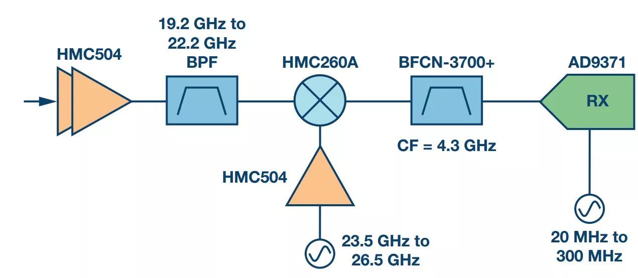
Figure 2. High IF (integrated TRx) with a bandwidth of up to 100 MHz.
This design can achieve a low noise figure and, due to its high integration, its design size is minimal. The performance is now summarized in Table 1.
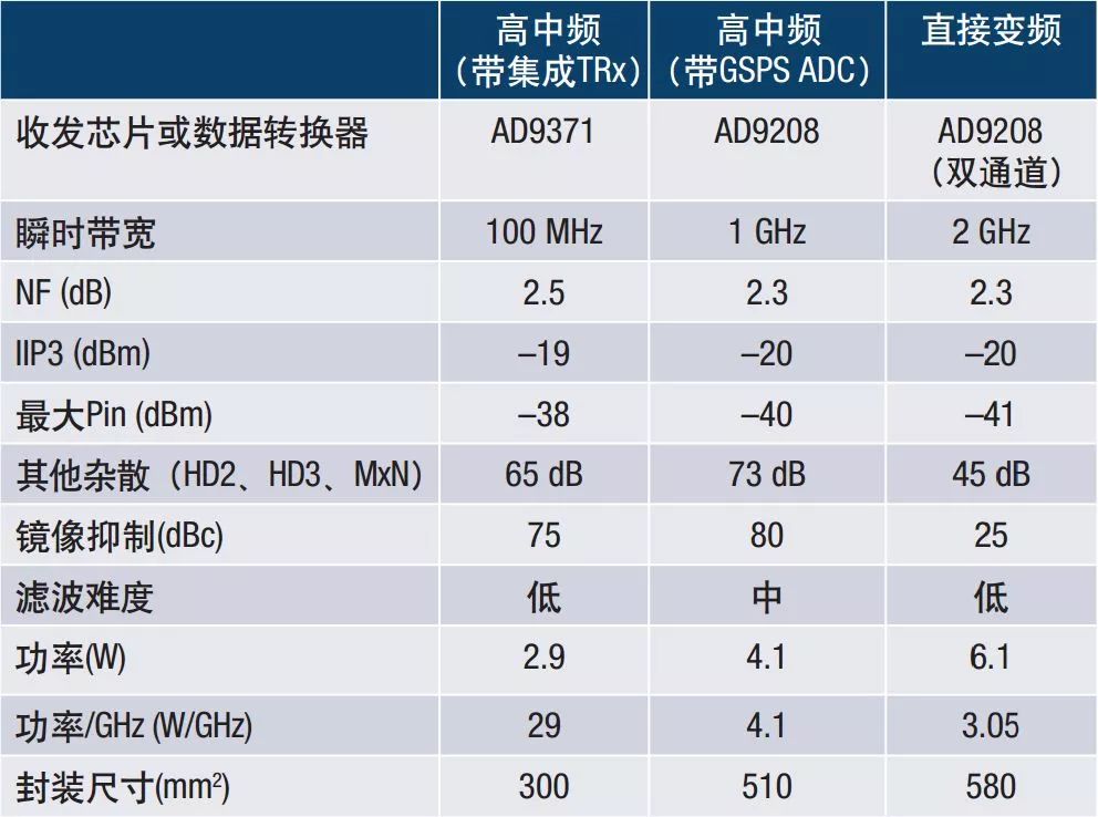
Table 1. Comparison of Ka Band Receiver Details
As hubs for multiple users of a satellite communication system, these systems may have to process multiple carrier signals simultaneously. In this case, the bandwidth or bandwidth/power of each receiver becomes very important. The signal chain shown in Figure 3 uses a high-speed ADC, the AD9208, which is a recently released high-sampling ADC that digitizes the instantaneous bandwidth of up to 1.5 Ghz. In this example, to achieve an instantaneous bandwidth of 1 Ghz, the intermediate frequency is placed at 4.5 GHz. The bandwidth achievable here depends on the filtering requirements of the anti-aliasing filter located before the ADC, but is generally limited to ~75% of the Nyquist zone (half the sampling rate).
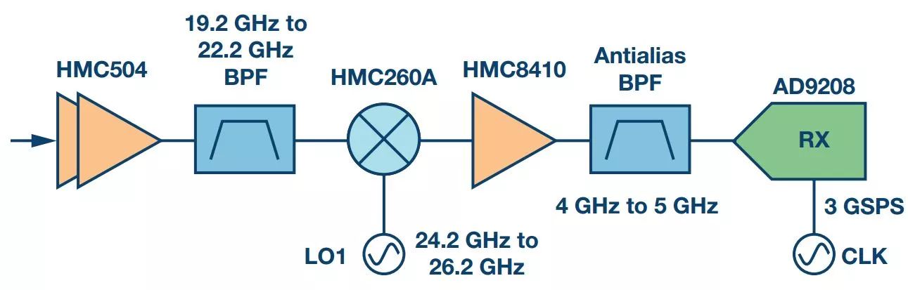
Figure 3. Single downconversion to high IF with GSPS ADC.
In systems that require the highest instantaneous bandwidth and may be at the expense of CNR, the signal chain shown in Figure 4 can be used. The signal chain uses an I/Q mixer, the HMC8191, which has an image rejection of ~25 dBc. In this case, image rejection performance is limited by the amplitude and phase balance between the I and Q output channels. This is a limiting factor for this signal chain without the use of more advanced Quadrature Error Correction (QEC) techniques. The performance of this signal chain is summarized in Table 1. It should be noted that NF and IP3 performance is similar to other options, but the power/GHz indicator is the lowest of the three, and the size is also optimal from the amount of bandwidth available at any time.
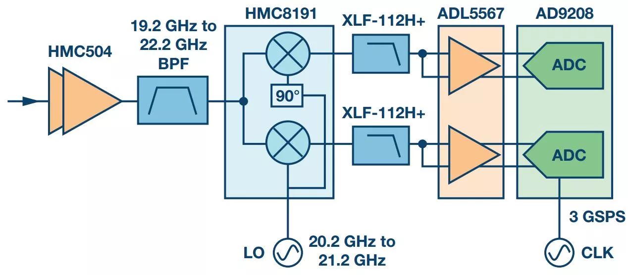
Figure 4. Direct conversion with I/Q mixer and GSPS ADC.
The three receiving options given here are shown in the following table, but it should be noted that this table does not list all possible options. The summary here is intended to show the differences between the various signal chain options. In any given system, the final optimal signal chain can be either one of the three or a combination of arbitrary options.
In addition, although only the receiver side is shown in the table, there is a similar trade-off in the transmitter signal chain. In general, after the system moves from a superheterodyne architecture to a direct conversion architecture, a trade-off between bandwidth and performance is required.
[Data interface]
After the data is digitized by the ADC or transceiver, it must be handed over to the system for processing via the digital interface. All of the data converters mentioned here use the high-speed JESD204b standard to receive signals from the data converter, then pack the signals into framing and transmit them over a small number of traces. The data rate of the chip varies depending on the system requirements, but all of the devices mentioned here have digital functions for decimation and frequency conversion that can be adapted to different data rates to meet different system requirements. This specification supports up to 12.5 GSPS on the JESD204b channel, and this is exploited by high-bandwidth systems that transmit large amounts of data. See the data sheet for the AD9208 and AD9371 for a detailed description of these interfaces. In addition, the choice of FPGA must consider this interface. Many FPGAs from vendors such as Xilinx® and Altera® have now integrated the standard in their devices, providing convenience for integration with these data converters.
[in conclusion]
This paper details the various trade-offs and lists some examples of the signal chains for the Ka-band satellite communication system. Several architectural options are also introduced, including the high-IF single-conversion option with the integrated transceiver AD9371, a similar architecture that replaces the integrated transceiver with GSPS ADC to improve instantaneous bandwidth, and direct improvements in bandwidth but reduced image rejection. Frequency conversion architecture. Although the signal chain introduced can be used directly, it is recommended to design it based on it. According to the specific system-level application, different requirements will appear. As the design work advances, the choice of signal chain will become more and more clear.
Nervos is an ambitious newcomer on the crypto market and Changelly has long watched it with interest. The project attracted the attention of investors and developers since its purpose is not to launch another cryptocurrency in the ecosystem. Nervos is a simple connecting database between any blockchains.
Nervos was launched in November 2019 by Nervos Network and aims to fix issues that plague both Bitcoin and Ethereum. Among them are scalability and value differences. To fix them, the Nervos team wants to implement effective scalability and raise the cost of their token by hosting other cryptocurrencies on their blockchain. Nervos supports smart contracts and is censorship-resistant. CKB is a native token of the Nervos network. It scales with the value of other assets stored on the network: the more cryptos and tokens are there, the more valuable CKB becomes. This means that this token will continue raising its value the more attention and assets it attracts. Add to that the support of smart contracts, and you have a nice crypto bridge between different blockchains. Which is exactly what makes it so attractive for both crypto enthusiasts and investors.
ckb mining machine,eaglesong algorythm,ckb miner,goldshel ck6,goldshell ck5
Shenzhen YLHM Technology Co., Ltd. , https://www.ylhm-tech.com