The AXI interface has five independent channels:
(1) Write address channel (AW): write address channel
(2) Write data channel (W): write data channel
(3) Write response channel (B) : write response channel
(4) Read address channel (AR): read address channel
(5) Read data channel (R): read data channel

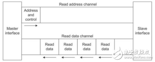
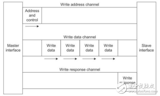
The five channel diagrams are:

Read address channel and read data channel

Write address channel, write data channel and write response channel
Read the signal of the address channel: S_AXI_ARADDR, S_AXI_ARPROT, S_AXI_ARVALID, S_AXI_ARREADY;
Read the data channel signal: S_AXI_RDATA, S_AXI_RRESP, S_AXI_RVALID, S_AXI_RREADY;
Write address channel signals: S_AXI_AWADDR, S_AXI_AWPROT, S_AXI_AWVALID, S_AXI_AWREADY;
Write data channel signals: S_AXI_WDATA, S_AXI_WSTRB, S_AXI_WVALID, S_AXI_WREADY;
Write the signal of the response channel: S_AXI_BRESP, S_AXI_BVALID, S_AXI_BREADY.
Bus width of the AXI interface:
C_S_AXI_ADDR_WIDTH : width of the S_AXI data bus
C_S_AXI_ADDR_WIDTH : width of the S_AXI address bus
Detailed description of the signal of the AXI interface:
S_AXI_ACLK : in std_logic;
Bus input clock signal
S_AXI_ARESETN : in std_logic;
Global reset signal, this signal is active low
S_AXI_AWADDR : in std_logic_vector(C_S_AXI_ADDR_WIDTH-1 downto 0);
Write address channel (sent by master setting to slave)
S_AXI_AWPROT : in std_logic_vector(2 downto 0);
Write channel protection type, this signal indicates the privilege and security level of the transaction, and whether the transaction is a data access or an instruction access.
S_AXI_AWVALID : in std_logic;
The write address is valid. This signal indicates that the master is transmitting a valid write address and control information.
S_AXI_AWREADY : out std_logic;
The write address is ready. This signal indicates that the slave device will accept the address and associated control signals.
S_AXI_WDATA : in std_logic_vector(C_S_AXI_DATA_WIDTH-1 downto 0);
Write data (transferred from the master device settings to the slave device)
S_AXI_WSTRB : in std_logic_vector((C_S_AXI_DATA_WIDTH/8)-1 downto 0);
Write data strobe, this signal indicates which byte channel on the write data bus holds valid data. Write a strobe bit for every eight bits on the write data bus
S_AXI_WVALID : in std_logic;
Write is valid, this signal indicates that valid write data and write strobe are available
S_AXI_WREADY : out std_logic;
Write ready, this signal indicates that the slave device can get the write data
S_AXI_BRESP : out std_logic_vector(1 downto 0);
Write response, this signal indicates the completion status of the write transaction
S_AXI_BVALID : out std_logic;
The write response is valid. This signal indicates that the channel is issuing a valid write response.
S_AXI_BREADY : in std_logic;
In response to the preparation, this signal indicates that the master device can accept the write response.
S_AXI_ARADDR : in std_logic_vector(C_S_AXI_ADDR_WIDTH-1 downto 0);
Read address (transferred from the master device to the slave device)
S_AXI_ARPROT : in std_logic_vector(2 downto 0);
Read channel protection type, this signal indicates the privilege and security level of the transaction, and whether the transaction is a data access or an instruction access.
S_AXI_ARVALID : in std_logic;
The read address is valid. This signal indicates that the read address channel is transmitting a valid read address and control information.
S_AXI_ARREADY : out std_logic;
Read address preparation, this signal indicates that the slave device is ready to accept the address and associated control signals
S_AXI_RDATA : out std_logic_vector(C_S_AXI_DATA_WIDTH-1 downto 0);
Read data (set by slave)
S_AXI_RRESP : out std_logic_vector(1 downto 0);
Read response, this signal indicates the completion status of the read data transfer
S_AXI_RVALID : out std_logic;
Read is valid, this signal indicates that the read data channel is transmitting the required read data
S_AXI_RREADY : in std_logic
Read ready, this signal indicates that the master device can accept read data and response information
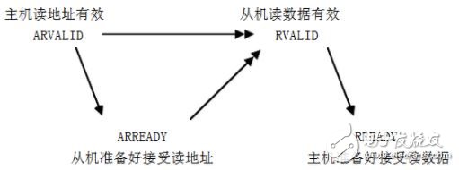
2. Dependencies between AXI bus channel handshake signalsAXI has a total of 5 channels, each channel has a pair of valid & ready signals, the sender uses the valid signal to indicate when the data and control information is valid, the receiver indicates the acceptable data and control information through the ready, the transmitted information occurs. In the case where vaild and ready are both high. Each channel can be independently handshaked, and the relationship between them is flexible. The read data must follow the address associated with its data, and the write response must occur after its associated write transaction.
Read transaction handshake dependencies are as follows:

Thermal Cutout,Capillary Type Thermostat,Freezer Used Thermostat,Adjustable Thermostat
Foshan City Jiulong Machine Co., Ltd , https://www.jlthermostat.com