What is common mode and differential mode?
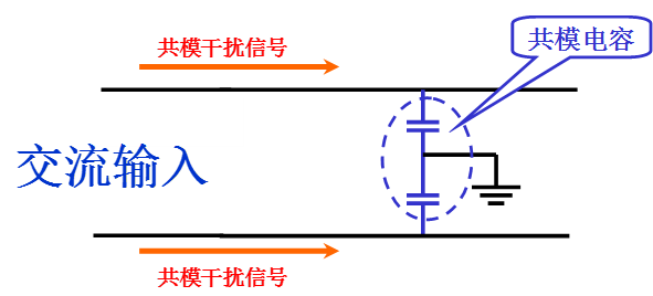
The communication line of the electrical equipment, the communication line of the telephone, etc., and the communication line exchanged with other equipment or peripheral equipment, have at least two wires, and the two wires are used as a round-trip line to transmit power or signals, usually outside the two wires. There is also a third conductor, which is the "ground line." There are two kinds of changes in voltage and current when passing through the wire. One is that the two wires are respectively transmitted as round-trip lines, which we call "differential mode"; the other is that two wires are used for the way, and the ground wire is used for return. Transmission, we call it "common mode."
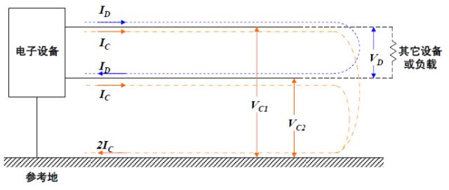
As shown above, the blue signal is transmitted back and forth between the two wires, which we call "differential mode"; and the yellow signal is transmitted between the signal and the ground, which we call "common mode".
Common mode interference and differential mode interference
The interference existing on any two power lines or communication lines can be represented by common mode interference and differential mode interference: common mode interference is transmitted between the wire and the ground (the chassis), which is an asymmetrical interference, which is defined as Undesirable potential difference between any current-carrying conductor and the reference ground; differential mode interference is transmitted between the two conductors, which is a symmetry interference, which is defined as the undesired potential difference between any two current-carrying conductors. . Under normal circumstances, the common mode interference has a large amplitude and a high frequency, and radiation can also be generated through the wires, resulting in large interference. The differential mode interference is small, the frequency is low, and the interference caused is small.
Common mode interference signal
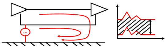
The currents of common mode interference are not necessarily equal, but the directions (phases) are the same. The external interference of electrical equipment is mainly based on common mode interference, and external interference is mostly dominated by common mode interference. Common mode interference itself generally does not cause harm to equipment, but if common mode interference is changed to differential mode interference, interference will be Serious, because the useful signals are differential mode signals.
Differential mode interference signal
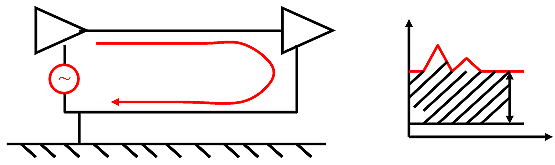
The differential mode interference currents are equal in magnitude and opposite in direction (phase). The differential mode current is converted to a common mode current due to the distributed capacitance of the trace, the inductance, the discontinuity of the signal trace, and the unexpected path of the signal return path.
Common mode interference causes
1. The grid is connected to the common mode interference voltage.
2. Radiated interference (such as lightning, equipment arc, nearby radio, high-power radiation source) induces common-mode interference on the signal line because the alternating magnetic field produces alternating current, ground-neutral loop area and ground. The line-fire line loop area is different, the two loop impedances are different, and the current magnitude is different.
3. The grounding voltage is not the same. Simply speaking, the potential difference creates a common mode interference.
4. Common mode interference caused by the internal lines of the equipment to the power line.
Common mode interference current
Common mode interference generally occurs in the form of common mode interference current. In general, there are three reasons for common mode interference current generation:
1. The external electromagnetic field induces a voltage on all the wires in the circuit trace (this voltage is equal amplitude and in phase with respect to the earth), and the current generated by this voltage.
2. The current generated by the ground potential difference due to the different ground potentials connected to the devices at both ends of the circuit trace.
3. There is a potential difference between the circuit traces on the device and the ground, so that common mode interference currents are generated on the circuit traces.
If the device generates a common mode interference current on its circuit trace, the circuit trace will generate strong electromagnetic radiation, which will cause electromagnetic interference to the electronic and electrical components, affecting the performance index of the product; in addition, when the circuit is unbalanced, The common mode interference current will be converted into differential mode interference current, and the differential mode interference current will directly affect the circuit. For the signal lines and their circuits in the circuit of electronic and electrical products: when the differential mode interference current flows through the wire loop in the circuit, it will cause differential mode interference radiation, which is equivalent to a small loop antenna and can be used in space. Radiating a magnetic field, or receiving a magnetic field.
How to identify common mode interference
1. Judging from sources of interference: Thunder, nearby arcs, nearby stations or other high-power radiating devices that cause interference on the cable are common-mode interference.
2. Judging from the frequency: Common mode interference is mainly concentrated above 1MHz. This is because common mode interference is sensed on the cable through space, and this induction is only likely to occur at higher frequencies. With one exception, low-frequency common-mode interference is also induced when the cable passes by a strong source of magnetic field radiation (for example, a switching power supply).
3. Measurement with the instrument: As long as there is a spectrum analyzer and a current caliper, it can be measured and judged. The steps are as follows:
a. Hold the current calipers on the signal line or ground (hot or neutral) and record the interference strength of an induced frequency (f1).
b. Hold the current caliper at the same time and block the signal line and the ground line. If the interference at (f1) can be observed, the (f1) interference contains the common mode interference component. To determine whether only the common mode interference component is included, proceed to step c. Discrimination.
c. Clamp the caliper to the signal line and the ground line respectively. If the amplitude of the (f1) interference measured on the two lines is the same, then (f1) interference only contains the common mode interference component; if not, then (f1) The interference also includes differential mode interference components.
How to suppress common mode interference
Common mode interference is the most common and harmful interference in EMC interference. The most direct way to suppress it is filtering, which is an important measure to suppress and prevent common mode interference. The function of the filter is to allow the signal of a certain frequency to pass smoothly, while the signal of other frequencies is greatly suppressed. It is essentially a frequency selection circuit, which cuts off the electromagnetic interference along the signal line or power line. The path, in addition, is an effective way to compress the interference spectrum. When the interference spectrum is different from the frequency band of the wanted signal, a filter can be used to filter out unwanted interference signals. Therefore, proper selection and proper use of the filter is important to suppress common mode interference.
If the useful signal is a differential mode signal and the interfering signal is a common mode signal, a common mode inductor can be used to reject the interfering signal:
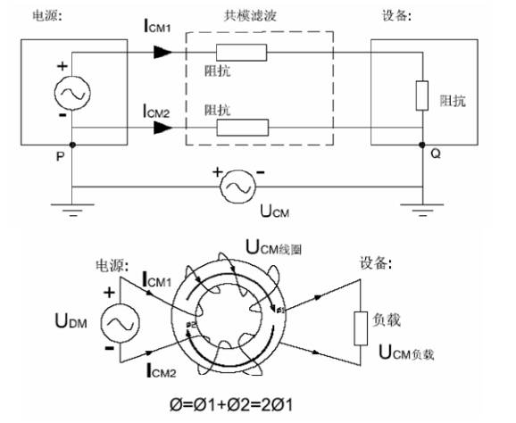
Principle of common mode inductance and suppression of interference
The common mode inductor is serially connected in the circuit. When there is a common mode interference current flowing through the coil, due to the same direction of the common mode interference current, the same magnetic field is generated in the coil to increase the inductance of the coil, so that the coil performance For high impedance, a strong damping effect is generated to attenuate the common mode interference current to achieve the purpose of filtering; when the normal differential mode current in the circuit flows through the common mode inductor, the current is in the common mode inductive coil wound in the same phase. The reverse magnetic fields are generated to cancel each other, and thus there is substantially no attenuation for the normal differential mode current.
Case Common mode interference suppression method on USB signal
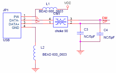
Filtering of USB ports - using common mode inductors
The signal on the USB transmission line is a differential signal and the interference source is a common mode interference signal. The common mode inductance on the transmission line can better suppress the common mode interference without any attenuation of the useful differential signal.
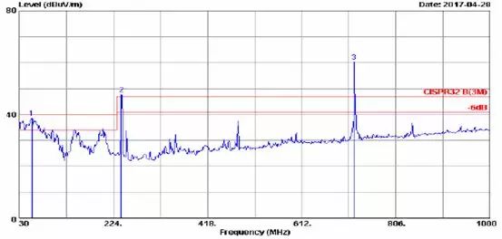
USB high speed operation produces strong common mode interference on the DM/DP signal line
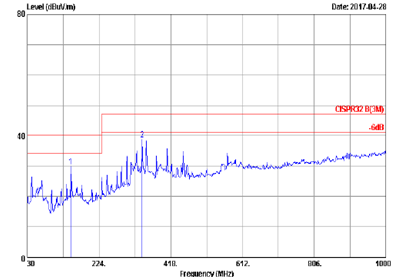
The common mode interference signal is effectively suppressed after the filter-common mode inductor is added to the circuit.
If the common mode interference source is in the power supply loop, common mode capacitors can be used to suppress the interference signal.
By introducing a common-mode capacitor into the circuit, the common-mode capacitor provides the shortest path for bypassing the common-mode interference signal, thereby suppressing common-mode interference.
If the power supply circuit also has differential mode interference, use differential mode capacitors to suppress interference.
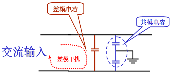
Introducing a differential mode capacitor in the circuit, the differential mode capacitor provides the shortest path to bypass the differential mode interference signal, thereby suppressing the generation of differential mode interference.
to sum up
Common mode interference is the most common and very harmful interference in EMC interference. In addition to filtering, the method of suppressing it can also reduce the common mode signal by shielding the signal line and reducing the ground line impedance on a large area of ​​the PCB. Strength and other methods. Regarding the selection and application of EMC components, we will make more introductions in the future, so stay tuned, thank you!
No.: 00111 material: Aluminum specification: 0-5m optional model: uqk-01l the principle of electronic liquid level switch is to detect the liquid level through the electronic probe, and then process the detected signal through the special liquid chip for level detection When the measured liquid reaches the action point, the chip outputs high-level or low-level signal, and then cooperates with the water level controller to control the liquid level No floating ball and reed, no external mechanical action, pollution resistance and durability, not afraid of the influence of floating objects It can be installed at any angle The vertical installation has certain anti - wave function and is suitable for immersion in water for a long time The working voltage is DC 5-24v, which is very safe This method is practical,
Level Measuring Controller,Magnetic Control Liquid Level Switch,Liquid Level Control Switch Module,Liquid Level Control Stainless Float Ball
Taizhou Jiabo Instrument Technology Co., Ltd. , https://www.jbcbyq.com