The main roads at the intersection are north-south and east-west. There are red, yellow and green traffic lights at each intersection and digital tubes showing the passage/stop countdown time. The function of the traffic light control system is as follows:
1) The working process of the signal light and the digital tube is: the red light in the north and south direction is 20 seconds (the digital tube counts down from 20), the green light in the east and west directions is 17 seconds (the digital tube counts down from 17), and then the yellow light flashes for 3 seconds (the digital tube is 3 countdown); when the yellow light becomes 0 seconds, the red light in the east-west direction is on for 30 seconds (the digital tube counts down from 30), then the north-south direction green light is on for 27 seconds (the digital tube counts down from 27), then the yellow light flashes for 3 seconds. (The digital tube counts down from 3); when the yellow light is 0 seconds, the red light in the north and south lights for 20 seconds, then the green light in the east and west directions is 17 seconds, and so on.
2) The transit time of the north-south and east-west directions can be adjusted (increase or decrease) by buttons;
3) According to the actual traffic flow, three different working hours can be set, which are “busyâ€, “not busy†and “freeâ€. The time of the traffic lights in the north and south and east-west directions in the three periods is different. “Busy†The time is greater than "not busy", "not busy" is greater than "free";
4) Three time periods are set by serial communication. The serial communication data format is two bytes. The previous byte represents the address, and the last byte represents the time period. The address bytes are 0x01, 0x02, 0x03, etc., which represent the addresses of different groups. The time slot bytes are: 0x00, 0x01, and 0x02, which indicate different time periods, namely, "free", "not busy", and "busy". For example, when transmitting data 0x01, 0x00, it means the "free" period of the first group.
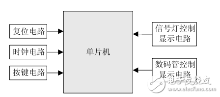
1, system hardware designThe whole system is mainly composed of main control center - Hongjing Technology STC89S52 single-chip microcomputer and reset circuit, clock circuit, signal light control display circuit, digital tube control display circuit and button control circuit and other functional modules. The system hardware block diagram is shown in Figure 1.

Figure 1 Block diagram of the hardware circuit structure of the traffic light control system
The reset circuit and the clock circuit are general-purpose circuit modules, and the crystal frequency is 11.0592 MHz.
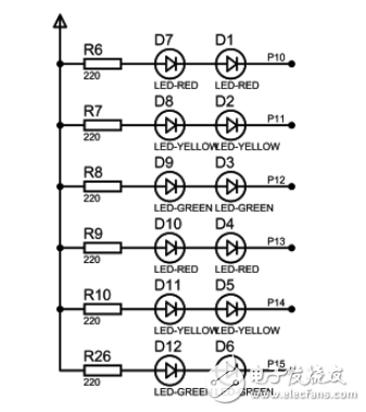
The signal control display circuit is shown in Figure 2. The 12 light-emitting diodes are controlled by P1.0~P1.5 in the P1 port of the single-chip microcomputer to simulate the actual traffic signal. Among them, P1.0~P1.2 control the red, yellow and green lights in the north-south direction respectively, and P1.3~P1.5 control the red, yellow and green lights in the east-west direction. All signal lights are connected by means of a common anode. When the corresponding ports of P1.0~P1.5 output low level, the corresponding LEDs illuminate, indicating the corresponding traffic state.

Figure 2 signal light control display circuit diagram
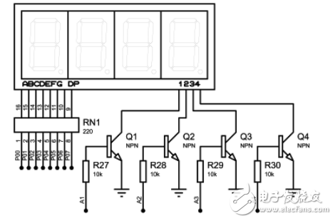
The 4-digit seven-segment digital tube is used to display the pass/stop countdown time. The digital tube control display circuit is shown in Figure 3. The 8-segment segment code of the digital tube is connected with the P0 port of the single-chip microcomputer, and the 4-bit bit code is connected with the MCU port (A1~A4) through the inverted phase of the triode. By controlling the bit code of each digital tube in turn, the digital tube is controlled to display the digital dynamics in turn. Since the digital tube is a common cathode connection, the segment code and the bit code are active high.

Figure 3 digital tube control display circuit diagram
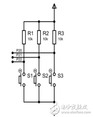
The function button circuit is shown in Figure 4. There are three buttons, S1, S2 and S3, which are connected to the P2.0~P2.2 ports of the MCU. The main function of the button is to manually adjust the transit time. Specifically: S1 is used for channel switching, 1 time is used to adjust the north-south direction, 2 times is used to adjust the east-west traffic time, and 3 times exit time is adjusted; S2 is used to increase the transit time, and each pass time is increased. 1S; S2 is used to reduce the transit time, and each pass time is reduced by 1S. Of course, the adjustment step of time can be any other value, such as 5s or 10s. The transit time setting has the longest time value and the shortest time value.

Figure 4 function button circuit diagram
Commutators For Industrial Motors
Commutators For Industrial Motors,Commutator For Fan Motors,Commutator For Switching Motors,Commutator For Auto
ZHEJIANG JIAGU ELECTRIC APPLIANCES CO. LTD , https://www.chinajiagu.com