1, the idea of ​​self-made power originated from the previous two days to try to calculate the amplifier, found that the power supply -12V is too high, resulting in the op amp can not work properly.
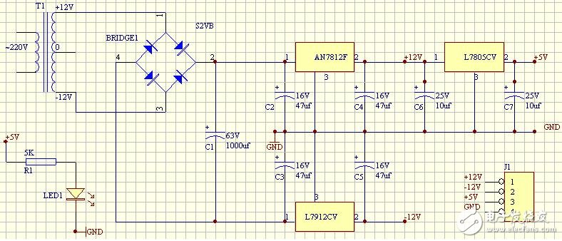
2, schematic

Figure 1, self-regulation circuit wiring diagram
Description: (1), T1 is a 10W positive and negative 12V transformer bought by the electronic market for 9 yuan. At first, I removed a small transformer from a bad computer power supply and thought it was usable. I first found that there were a lot of pins. I couldn’t tell which one was primary and secondary. Secondly, I boldly put only two leads at one end. The foot is connected to the 220V as the primary coil, just a touch of contact, and the room jumps when it is open. Later, I realized that it is a so-called high-frequency transformer. When working, it rectifies 220 AC power, and after filtering, it is input through the high-frequency switch. Small size and high power can be achieved when the features are available. Give a beginner like me a wake-up call, be careful when you encounter this kind of problem! Sure enough, the new transformer bought in the electronics market, only 10w! ! ! So big! :)
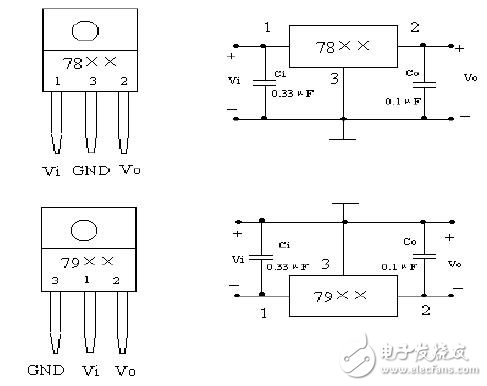
(2), 7812 and 7912 are common parts, but the pin definition is quite messy. In short, the correspondence is good. Figure 2 is what I found when I did the whole thing. If I think it is clear, I will extract it. Connecting the wrong pin may cause the voltage at both ends to be asymmetrical, even at the rear of the rectifier bridge. In fact, the correct wiring, the voltage regulation effect is very good.

Figure 2, 78xx and 79xx wiring diagram
(3), rectifier bridge can be bought, on an integrated circuit, I bought S2VB20, can pass 200VDC, 2A current, anyway, my transformer is 10W output 1A less than enough!
(4), filter capacitors, it seems that there is nothing to pay attention to, some people say that from a few hundred to several thousand micro-methods, but pay attention to the pressure, do not be broken down. Also, don't reverse, between 0 and -12v, 0 is connected to the positive capacitor and -12 is negative. I reversed, and a capacitor broke out with smoke. The filtering effect is quite good, no load! I can't see it. I will take a look at this filter in the future. I don't know what special features are available. Look at a straight line with an oscilloscope If the capacitor is not solved, it can be clearly seen that the waveform of the negative half-axis after the rectifier bridge is flipped up. After adding the capacitor, it immediately becomes a straight line.
(5), 78xx and 79xx, the capacitance between 1, 2 and ground, there are books on the prevention of high-frequency self-oscillation and suppression of input high-frequency interference signals, extracted here. The size of the capacitor is also randomly selected. Please do not refer to this.
3, the results
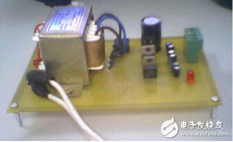
After debugging, the power supply can output DC11.80V, DC-12.11V, Dc+5.02 three-way DC voltage source. The total output power is 10W. Unfortunately, there is no access fuse. Do not use the power supply to burn it. It is good to use it to re-edit the op amp. Figure 3 is a photo of the real thing, the little girl is not in school, the camera is not in, can only use the mobile phone to deal with it :)

Figure 3 homemade power supply photo
Zinc rod high purity of over 99.995% was widely used in vacuum coating and other purposes.
Zinc Rod,Pure Zinc Rod,Zinc Anode Rod,Zinc Welding Rod
Shaoxing Tianlong Tin Materials Co.,Ltd. , https://www.tianlongspray.com