Application of Open Type Current Transformer in Low Voltage Distribution System

Application of Open Type Current Transformer in Low Voltage Distribution System
Wu Jianming Yang Guangliang Huang Wentao
Jiangsu Ankerui Electric Appliance Manufacturing Co., Ltd., Jiangyin, Jiangsu 214405, China;
Abstract: This paper analyzes the principle of low-voltage open current transformers and analyzes the application of opening current transformers in low-voltage power distribution systems with engineering examples. It is mainly the application and construction details of the retrofit projects, providing solutions for users to quickly realize intelligent power distribution. The scheme has the advantages of low cost, low investment and easy installation and connection, which is beneficial to the further promotion and application of low-voltage intelligent power distribution.
Keywords: Open-type current transformer Low-voltage distribution system transformation project Principle of operation Application construction details
1. Introduction Currently, most of the low-voltage current transformers in the market are mainly used for the construction of new projects. Due to the rapid economic development, enterprises have gradually increased their awareness of energy conservation and emission reduction. The electrical characteristics of many companies are:
1 The electrical cabinet has been operating for a long time;
2 Most of the current transformers only measure the system current, and there is no corresponding metering device and protection device. The metering device only has a general table of the power supply bureau, but it cannot evaluate all the power of the workshop, and the system circuit protection device does not have any;
3 The APF active filter provides the acquisition signal when the harmonic content is relatively large;
4 Most of the line trunks are large-size copper bars. The demolition requires a lot of manpower and time, and it is inconvenient to install conventional current transformers.
5 The company's production time is relatively tight, and it cannot be interrupted for a long time.
Therefore, if it is necessary to retrofit the above-mentioned electrical, the use of open current transformers can save a lot of investment for the user.
2 Product Design
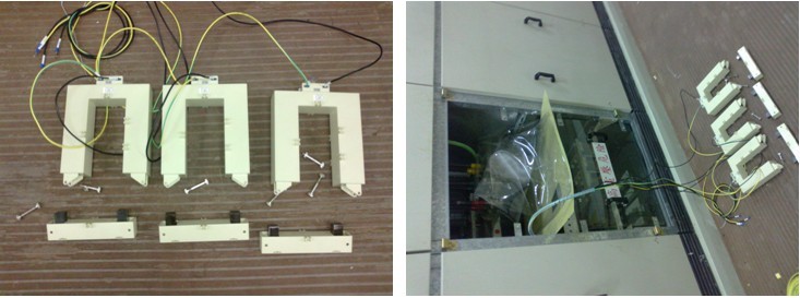
2.1 Structural Features This product has a novel structure, elegant appearance and convenient design and transparent wiring. The shell material adopts PC/ABS alloy, which has the characteristics of high temperature resistance, high mechanical strength and environmental protection; the core adopts oriented cold rolling silicon steel sheet, which has the characteristics of stable performance, high mechanical strength, high magnetic permeability, etc.; the enameled wire in the skeleton coil is adopted. High-strength enameled wire, with high dielectric strength, high temperature resistance and other characteristics, the specific structure shown in Figure 1. Open type current transformers are developed on the basis of conventional low voltage busbar current transformers. Compatible cables and copper bar mounting methods are available. According to the measurement range of primary current, 100A-5000A adopts a split type design scheme. The main specifications are K-30. ×20, K-08×50, K-80×80, K-120×60, K-120×80, K-160×80, K-200×80.
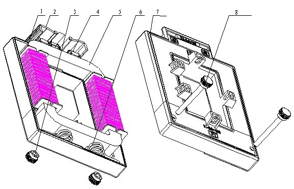
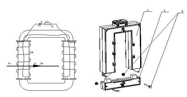
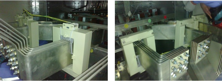
figure 1
1- Skeleton coil, 2-transparent flip, 3-mounting nut, 4-terminal,
5-core, 6-spring, 7-shell, 8-mounting screws.
2.2 Open Current Transformer Working Principle
The working principle of the open low voltage current transformer is shown in Fig. 1. The primary winding of the open current transformer is connected in series in the measured line. I1 is the primary current of the current transformer, which is the line current, and N1 is the number of turns of the current transformer. Secondary current of I2 current transformer (usually 5A, 1A), N2 is the secondary number of turns of the current transformer, Z2e is the impedance of the secondary circuit device and the connecting wire. When the primary current flows in from the current transformer P1 end, P2 end, in the case of the second Z2e is connected, by the principle of electromagnetic induction, the secondary winding of the current transformer has a current I2 flowing from S1 through Z2e to S2, Form a closed loop. This results in an ideal current I1×N1=I2×N2, so that I1/I2=N1/N2=K, and K is the ratio of the current transformer. However, since the iron core of the open type current transformer is cut, the performance of the core will be more severe, so the cross-sectional area of ​​the core of the transformer must be increased, and the number of ampere turns must be increased, and I1×N1=I2 ×N2≥100AN.
Figure 2 Figure 3
Note: The upper body of 1-open current transformer in Fig. 3, the lower body of 2-open current transformer, 3- mounting screw, nut

2.3 Product Installation
As shown in Figure 3, the installation screw and nut of the transformer are opened, the lower body of the transformer is removed, the upper body of the transformer is loaded into a busbar of the power distribution system, the lower body of the transformer is closed, and the transformer is Install the screws through the fixing holes in the upper and lower body of the transformer, and tighten the nuts to fix the upper and lower bodies of the transformer together. Then, the mutual inductor is fixed on the busbar through the mounting and fixing holes on both sides of the transformer. Complete the transformer installation. The secondary of the transformer is then connected to the measuring device. The whole process is quick and easy.
3. Application
The open current transformer is mainly used in the low voltage distribution transformation project. The open current transformer has the same output as the conventional closed transformer as the standard 5A or 1A. The measurement accuracy is high and the capacity is large. It can be used with measuring instruments and meters. Strong product overload capacity can be used with the device.
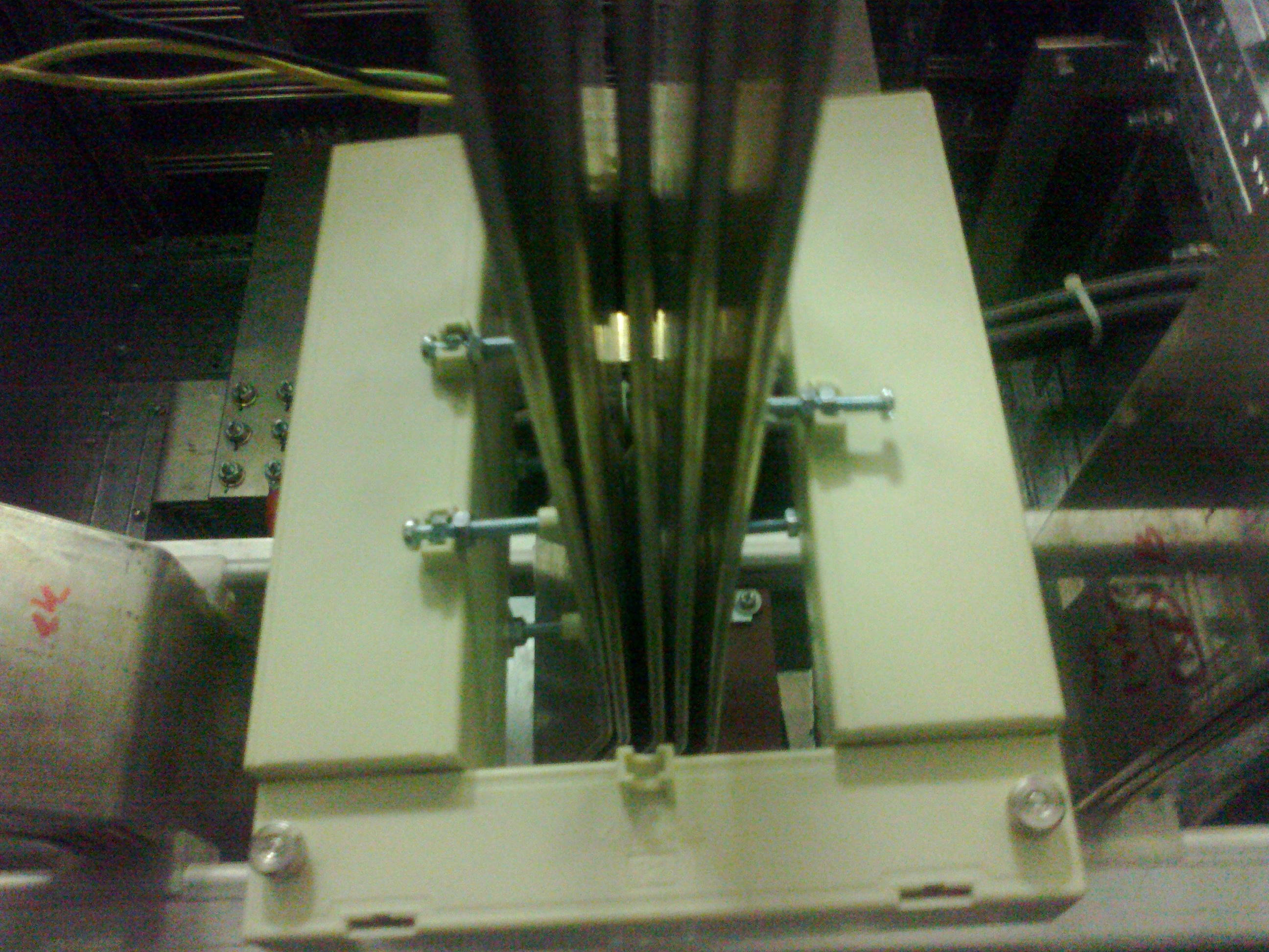
3.1 Application Examples
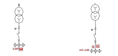
Solution (1): Taking the low-voltage feeder of a company in the semiconductor industry in Shanghai as an example. As shown in Figure 4, each feeder needs to measure three-phase current and supply the current signal to the relay to prevent system current overload or short circuit. The primary busbar specification for phase A, phase B, and phase C of each feeder is 120×10×3, copper height is 1.5 meters, rated current per phase is 2500A, and AKH-0.66/120×50II closed type current transformer is adopted. The current signal is collected. During construction, each phase of the copper bar must be disassembled. Each phase copper bar has a weight of 480 kg. Therefore, the installer needs at least 2 people. It takes at least 3 hours to complete the disassembly. The transformers are installed for 20 minutes and it takes 3 hours to install the copper bar. Then each feeder needs at least 19 hours to be installed, and the factory must power off for about 20 hours.

Figure 4 Figure 5
Scheme (2), taking the same low-voltage feeder of a company in the semiconductor industry as an example. As shown in Figure 5, each feeder needs to measure three-phase current and supply the current signal to the measuring instrument. The primary busbar specification for phase A, phase B, and phase C of each feeder is 120×10×3, copper height is 1.5 meters, rated current per phase is 2500A, and AKH-0.66/K-120×60 open type current is used. Transformer current signal acquisition, construction, do not need to remove each phase of copper, an installation staff as long as the transformer to open the installation screw \\\\\\\\\\\\\\\\ nut, the transformer sets in On the busbar, close the transformer and fix it with the screw \\\\\\\\\\\\\\\\. Then fix the transformer on the busbar. The whole process takes only 30 minutes. Only when the installation of the wiring is completed, the dismantling is completed, and the power outage at the factory only takes about 40 minutes. Therefore, the cost of each feeder of the above scheme is shown in the table (1).
Table I)
3.2 Construction details According to the parameters in the above product specification of our company, and according to the actual situation of the user site, select the appropriate opening current transformer to connect the relay or measuring instrument with the open current transformer for protection, and ensure the current transformer two. Can not open the way, the open current transformer upper and lower parts are open, and pay attention to the current transformer P1 surface, the next two parts consistent, and the relay installed in the field, all the site is placed, a large current bus Wear copper bars to wait for power outage, as shown below:
After the power failure, the open current transformers of all circuits are all installed on the busbar at the same time. The upper and lower parts of the open current transformer are installed by screws and nuts as shown in the following figure:
Finally, the open current transformer is fixed on the busbar through our standard accessories, and the relay output signal line is connected to the auxiliary contact of the circuit breaker to complete the installation process. As shown below:
To sum up, the use of open current transformers in the renovation project is the most cost-effective, and it can quickly realize low-cost intelligent multi-loop monitoring of low-voltage power distribution, which is conducive to the further promotion and application of low-voltage intelligent power distribution.
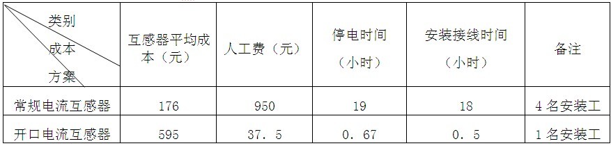
4 Conclusion Open-type current transformers have been applied in engineering distribution monitoring systems in industrial and mining enterprises in Shanghai, Suzhou, Shenzhen, Yunnan, Chongqing, Hangzhou, Tianjin, Jinan, Xi’an, and Inner Mongolia to reduce investment costs and produce better results. The social and economic benefits.
Article from: "Electrical Technology" 2012 No. 8.

Piezoelectric Buzzer For Driver Circuit Built-in

The piezoelectric buzzers (for Driver Circuit Built-in) offer optimal sound, performance, and efficiency for all types of medical and industrial applications. Our piezo buzzers are constructed in a variety of sizes and work across varying frequencies which allows them to produce different sounds and tones. As voltage is applied to a piezo Buzzer, the piezoceramic disc vibrates, flexing with respect to input voltage to generate sound. Our piezo buzzers maintain low current draw which is advantageous for any battery operated device. Since piezo buzzers don`t have a magnet in their construction, it eliminates EMI/EMC issues.

Buzzer Alarm,Built In Piezoelectric Buzzer,High Frequency Alarm Buzzer,Constant Tone Buzzer For Alarm

Jiangsu Huawha Electronices Co.,Ltd , https://www.hnbuzzer.com