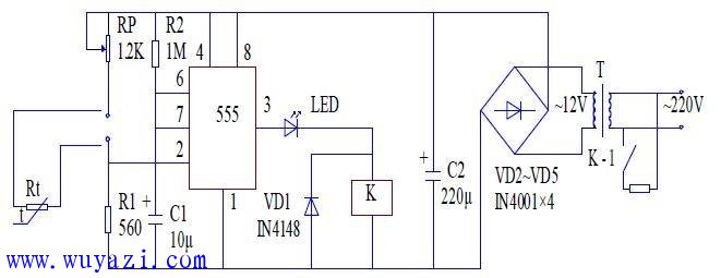
Circuit operation principle: After diode VD2~VD5 rectification and capacitor C2 filtering, the voltage of the control part of the circuit is about 12V. The 555 time base circuit is connected to a monostable flip-flop with a transient state of 11 s.
Set the control temperature to 25oC, and adjust the potentiometer RP so that RP + Rt = 2R1, Rt is a thermistor with a negative temperature coefficient. When the temperature is lower than 25oC, the Rt resistance rises, and the 2 pin of the 555 time base circuit is low level, then the 3 pin changes from the low level output to the high level output, the relay K turns on, and the contacts are attracted. The heating tube starts to heat up until the temperature returns to 25oC, the Rt resistance becomes smaller, the 2 pin of the 555 time base circuit is at a high level, the 3 pin outputs a low level, the relay K is de-energized, the contact is disconnected, and the heating stops.

Square Hole Breadboard,400 Tie Point Breadboard,Makeronics Breadboard,Small Solderless Breadboard
Cixi Zhongyi Electronics Factory , https://www.cx-zhongyi.com