Author: TT Electronics product line director, sensing and control TH Swee
In many new car designs, hydraulic power steering systems are being replaced by electric power steering systems (EPS). In the passenger car market, the use of electric motors to drive bogies is largely due to improved fuel economy (although small). Because there is no hydraulic oil to process, EPS also helps achieve green, environmentally friendly, non-polluting end of vehicle life. It also continues to use a computer-controlled, wire-driven drive system that starts with anti-lock braking and traction control and is now leading us to fully automate the vehicle.
Despite the lack of experience in the design of early EPS and the lack of “feeling†in these designs, it is widely believed that improvements in electric power steering systems and improvements in sensors and control technology have overcome this concern. Now, for most car drivers, if the driver does realize or can tell the difference, the EPS can provide the same performance as the hydraulic assist system.
This is a good system for small road vehicles, but for large commercial vehicles, such as buses and trucks, it has to be a different matter. For industrial off-road vehicles (ORVs), the system may face more stringent challenges; such as those used in mining and quarrying, agriculture, factories and warehouses. The problem is that providing steering assistance requires higher torque and the need to ensure the reliability of vehicles with higher mileage, heavier loads or more constant use than normal passenger cars.
In addition, some commercial or industrial vehicle applications may employ autonomous or semi-autonomous driving techniques earlier than regular road vehicles, making EPS a prerequisite. Long-haul freight is one of the early candidate applications; however, factories and warehouses have adopted this technology, in which forklifts are rapidly being replaced by unmanned vehicles, which are completely computer controlled.
The reliability of commercial vehicles throughout their useful life is critical to the adoption of EPS, which must be more durable to avoid malfunctions or any safety-critical accidents. A regular passenger car may travel 160,000 kilometers throughout its life cycle, and some commercial vehicles are expected to exceed 400,000 kilometers in three years. In addition, the operating environment of commercial vehicles is more prone to noise and vibration, which puts higher demands on the performance and reliability that EPS systems must deliver.
Commercial vehicles and off-road industrial vehicles have heavier steering loads, which require higher power assistance. The steering column mounted EPS unit typically produces a force of approximately 5 kN. Moving the EPS closer to the wheel to drive the pinion shaft or bogie can increase it to between 5 kN and 12 kN, but will subject the EPS to higher temperatures and vibrations. Larger vehicles may require more force, at least 15 kN, which may be greater for the most demanding off-road applications. EPS systems for such vehicles will need to operate from higher voltages, such as 42 V, and can provide output power greater than 3 kW.
Commercial vehicle EPS requires better sensors
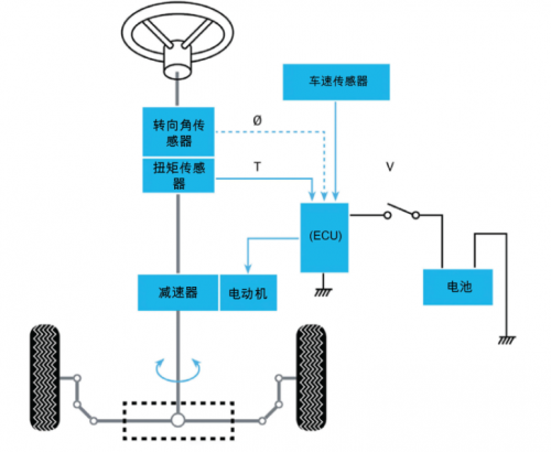
An integral part of the EPS system design is the sensor used to detect the angular position of the steering wheel and the torque applied to the steering column, pinion or rack. Vehicle speed is another factor that the algorithm implemented by the EPS Electronic Control Unit (ECU) needs to consider when driving an EPS motor, because at lower speeds less force is required to achieve the same change in direction. As shown in Figure 1.

Figure 1. Typical schematic of an electric power steering system (EPS)
Rotating torque and position sensors using sliding electrical contacts have some problems due to vibration, and if these problems have become apparent, the problem will be even worse for commercial vehicles. As part of the column-mounted EPS system, they can also help reduce cabin noise, which is less than 40 dB for passenger cars. A better solution is to use a non-contact position and torque sensor based on the magnetic induction principle and mount it on the bogie. The advantage of this solution is that the system is less affected by vibration, which reduces noise and improves reliability.
Better yet, TT Electronics' combined Magnetorque Plus steering sensor is designed for rack-based EPS systems and can be customized for larger axes such as axles in trucks, buses and ORVs. This innovative sensor has been rigorously tested to meet the vibration challenges faced by commercial vehicles and has been shown to withstand 5G acceleration on the x-axis, z-axis and y-axis for 8 hours per axis. The sensor provides +/-5 torque resolution, enabling the ECU to achieve extremely smooth output. The angle of rotation can also be customized. For a car, 2.5 turns is usually sufficient, but for commercial vehicles, up to 4 turns may be required.
Hall effect technology provides a solution
Both non-contact position and torque sensing can be achieved using Hall effect technology, which detects the effect of the magnetic field on the current carrying conductor and produces a voltage difference across the current across the conductor. The Hall effect sensor is implemented as an integrated circuit IC in which the influence of magnetic force on charge carriers in the semiconductor can be measured as the output voltage of the chip.
Thus, the angular position and rotation of the shaft can be measured by suitable arrangements of Hall sensors and magnets using assemblies including rotating and stationary elements, namely the rotor and stator. For EPS applications, the assembly can be mounted on a steering column, pinion shaft or bogie. Designed for rack-mounted EPS, TT's Magnetorque Plus sensor combines non-contact torque and multi-turn position sensing into a rugged unit that is ideal for the more demanding and demanding requirements of larger vehicles.
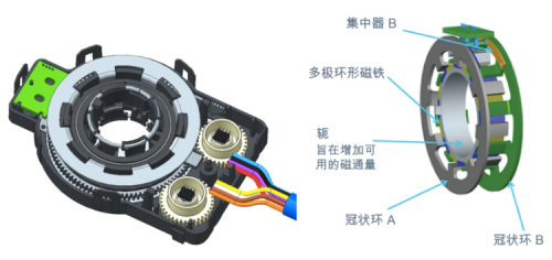
Figure 2 shows the overall structure of the sensor, while Figure 3 provides a more detailed description of the rotor components. The crown rings rotate together in the position rotor assembly, while the magnets and yokes designed to increase the available magnetic flux rotate together in the torque rotor assembly, but are separated from the position rotor.

Figure 2. Inside the Magnetorque Plus sensor Figure 3. Components of the rotor assembly
The Hall sensor for position sensing is located on the circuit board in the stator assembly above the two pinions that can be seen in Figure 2. They sense the magnetic flux of the magnets on the pinion. Based on these signals, a microprocessor calculates three outputs, two of which provide a high resolution angular position signal, and a third output that is a steering count signal that provides more than ± Absolute multi-turn position information of 900°.
For torque sensing, the crown ring shown in Figure 3 captures magnetic flux from the ring magnet of the torque rotor and directs the magnetic flux through a concentrator to a Hall sensor on another stator circuit board (shown in green in Figure 2) . The torque rotor is located on the steering shaft and does not make mechanical contact with any other components in the sensor assembly. The concentrator is stationary, so the magnetic flux flows from the magnet to the first crown ring and concentrator, then through the Hall sensor to the second concentrator and the crown ring, and then back to the magnet.
In order to increase the magnetic flux on the concentrator, the crown ring is arranged to ensure that the first crown ring is located on the north pole of the magnet and the second is located on the south pole. Thus, if the magnet rotates such that the two concentrators are centered on the line between the north pole and the south pole, zero flux flows through the Hall chip. In any intermediate position, the magnetic flux flowing through the Hall sensor will be proportional to the relative angle of rotation between the torque rotor assembly and the position rotor assembly. This provides the required measurement of the torque applied to the steering wheel.
in conclusion
Electric power steering systems are increasingly used in passenger cars, but their use in heavy commercial and industrial vehicles has been slow. These applications, especially for industrial off-road vehicle types, face special challenges that require reliable, long-life operation in harsh environments and provide precise responsive control.
TT's Magnetorque Plus combined position and torque sensor fulfills all of this. Its true, non-contact design maximizes mechanical durability and ensures a service life of at least 1 million axes without degrading the output signal. Its position sensor provides multi-turn position information with a torque sensor resolution range of +/-5°. System accuracy can be improved with customer-programmable torque offset and custom torque output slope along with other custom design options.
TT Electronics' integrated approach is smaller, lighter, and more cost-effective than alternatives using two independent sensors. This fully calibrated solution simplifies the design of EPS systems to meet the more demanding requirements of larger vehicles.
KNB6-63 Miniature Circuit Breaker
KNB6-63 Mini Circuit breakers, also named as the air switch which have a short for arc extinguishing device. It is a switch role, and also is a automatic protection of low-voltage electrical distribution. Its role is equivalent to the combination of switch. Fuse. Thermal Relay and other electrical components. It mainly used for short circuit and overload protection. Generally, According to the poles, mini Circuit breaker can be divided into 1P , 1P+N , 2P, 3P and 4P.
KNB6-63 Miniature Circuit Breaker,Electronics Miniature Circuits Breaker,Automatic Miniature Circuit Breaker,Mini Circuit Breaker
Wenzhou Korlen Electric Appliances Co., Ltd. , https://www.zjthermalrelay.com