Switch mode dimmable LED drivers are known for their high efficiency and precise control of LED current. This type of LED driver also provides dimming, allowing end users to reduce their power consumption while creating fantastic lighting effects. 8-bit microcontroller (MCU)-based solutions provide the necessary modules for such applications, enabling communication, customization, and intelligent control. In addition, integrated core-independent peripherals provide significant flexibility compared to pure analog or ASIC implementations, extending the functionality of lighting products while shaping product differentiation for innovation. This type of intelligent lighting solution with features such as fault prediction and maintenance, energy monitoring, color temperature maintenance, and remote communication and control is so numerous that it will be favored .
While LED drivers have many advantages over previous lighting solutions, there are many challenges in their implementation. But you don't have to worry, after reading this article, you will learn how to use 8-bit MCUs to easily address these design challenges, creating a high-performance switch-mode LED driver solution that is so rich that traditional solutions can only be seen .
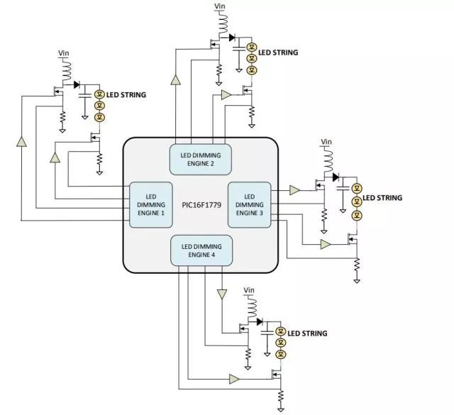
The 8-bit microcontroller can independently control up to four LED channels, a unique capability not found in most off-the-shelf LED driver controllers. In Figure 1, the LED dimming engine can be constructed from peripherals provided in a microcontroller. These engines have separate, closed channels that require little or no central processing unit (CPU) intervention to control the switch mode power converter. This frees up the CPU to perform other important tasks, such as monitoring, communication, or new intelligence in the system.

Figure 1: Graphical representation of four LED strings controlled by Microchip's PIC16F1779 8-bit microcontroller
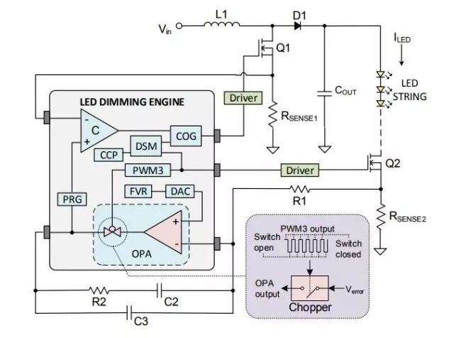
LED dimming engineIn Figure 2, the LED driver based on the current mode boost converter is controlled by an LED dimming engine. The engine is mainly composed of a complementary output-issuing generator (COG), a digital signal modulator (DSM), a comparator, a programmable ramp generator (PRG), an operational amplifier (OPA), and a pulse width modulator 3 (PWM3). The kernel's peripherals (CIP) are composed. These CIPs are combined with other on-chip peripherals such as fixed voltage regulators (FVRs), digital-to-analog converters (DACs), and capture/compare/PWM (CCP) to form a complete engine. The COG supplies a high frequency switching pulse to the MOSFET Q1 to transfer energy and supply current to the LED string. The switching period of the COG output is set by the CCP and duty cycle to maintain the constant current of the LED, depending on the comparator output. The comparator generates an output pulse whenever the voltage across Rsense1 exceeds the output of the PRG module. The input to the PRG is derived from the OPA output in the feedback circuit, which is configured as a slope compensator to counteract the effects of the intrinsic subharmonic oscillations when the duty cycle is greater than 50%.
OPA module implemented error amplifier (EA) having a Type II compensator configuration. The FVR is used as a DAC input to provide a reference voltage for the OPA non-inverting input based on the LED constant current specification.
For dimming purposes, PWM3 acts as a modulator for the CCP output while driving MOSFET Q2 to cause the LED to cycle quickly and extinguish. The modulation operation can be done by the DSM module, and the modulated output signal is fed to the COG. PWM3 provides a variable duty cycle pulse that controls the average current of the driver and actually controls the brightness of the LED.
The LED dimming engine not only performs the functions of a typical LED driver controller, but also has the ability to solve typical problems with LED drivers. Now we will explore these issues and analyze how to use the LED dimming engine to avoid them.

Figure 2. LED dimming engine
StrobeStrobe is one of the challenges that can be faced with a typical switch mode dimmable LED driver. While a well-planned strobe can have interesting effects, if the LED slams unexpectedly, it will ruin the user's desired lighting design. To avoid strobing and provide a smooth dimming experience, make sure that the drive's dimming effect from the highest gear (ie 100% light output) to the lowest gear is continuous and smooth. Since the LED responds to current changes instantaneously and does not have a damping effect, the driver must have enough dimming gear to ensure that the human eye does not notice the change. To meet this requirement, the LED dimming engine uses PWM3 to control the dimming of the LEDs. PWM3 is a 16-bit resolution PWM with a total of 65,536 gears from 100% to 0% duty cycle to ensure smooth switching of brightness.
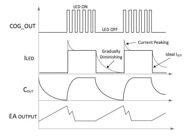
LED color temperature conversionThe LED driver can also convert the color temperature of the LED. This color change is perceived by the human eye and undermines the customer's claim to enjoy a quality LED lighting experience. Figure 3 shows a typical PWM LED dimming waveform. When the LED is off, the LED current will gradually decrease as the output capacitor slowly discharges. This event causes the LED to drift in color temperature and increase power consumption.

Figure 3. LED dimming waveform
A load switch can be used to prevent the output capacitor from slowly discharging. For example, in Figure 2, the circuit uses Q2 as the load switch, and the LED dimming engine synchronously turns off the COG PWM output and Q2 to cut off the current decay path and let the LED go out quickly.
Peak currentWhen a switch mode power converter is used to drive the LED, a feedback circuit is used to regulate the LED current. However, if improperly operated during dimming, the feedback circuit produces a peak current (see Figure 3). Referring back to Figure 2, when the LED is lit, current is delivered to the LED and the voltage across RSENSE2 is fed to the EA. When the LED is off, no current is transferred to the LED and the RSENSE2 voltage becomes zero. During this dimming, the EA output is increased to the maximum value and the EA compensation network is overcharged. When the modulated PWM is turned on again, if a high peak current is driven to the LED, it takes several cycles to recover. This peak current will reduce the life of the LED.
To avoid this problem, the LED dimming engine allows PWM3 to be used as a rewrite source for OPA. When PWM3 is low, the output of EA is tri-stated, completely disconnecting the compensation network from the feedback loop, and will maintain the last stable feedback point as the charge stored in the compensation capacitor. When PWM3 is high and the LED is lit again, the compensation network reconnects and the EA output voltage immediately jumps to its previous steady state (before PWM3 is low) and the LED current setpoint is restored almost immediately.
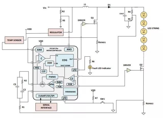
Complete solutionAs mentioned earlier, LED dimming engines require little or no CPU intervention to function properly. Therefore, when all control operations for the LED driver are assigned to the respective CIPs, the CPU will have sufficient bandwidth to perform other important tasks. In addition, protection functions such as undervoltage lockout (UVLO), overvoltage lockout (OVLO), and output overvoltage protection (OOVP) can be performed by processing the detected input and output voltages. This ensures that the LED driver operates according to specifications and that the LED is not affected by abnormal input and output conditions. The CPU can also process temperature data from the sensors to achieve thermal management of the LEDs. Moreover, when setting the dimming level of the LED driver, the CPU can process trigger signals from simple external switches or serial communication commands. In addition, the parameters of the LED driver can be sent to an external device for monitoring or testing by serial communication.
In addition to the above features, designers can add more intelligent features to their LED applications, including communications (eg DALI or DMX) and custom control functions. Figure 4 shows an example of a complete switch mode dimmable LED driver solution using an LED dimming engine.

Figure 4. Switching Mode Dimmable LED Driver Solution
in conclusionThe LED dimming engine can be used to create high efficiency switch mode dimmable LED drivers. Efficient in its ability to drive multiple LED strings, provide efficient energy, ensure optimal LED performance, maintain long LED life and add intelligence to the system.
Business Style Leather Phone Case
Business Style Leather Phone Case,Cover Leather Case,Flip Cover Leather Case,Genuine Leather Case
Guangzhou Jiaqi International Trade Co., Ltd , https://www.make-case.com