Today, traffic lights are installed on various roads and have become the most common and effective means of diverting traffic vehicles. But this technology has appeared in the 19th century. In 1858, red and blue mechanical wrench-type signal lights, which were powered by gas as a light source, were installed on the main streets of London, England, to command carriages. This is the world's first traffic light. In 1868, British mechanical engineer Nayt installed the world's first gas traffic lights on the square in front of the Parliament Building in Westminster, London. It consists of red and green with a rotating square glass lantern, red for "stop" and green for "attention". On January 2, 1869, the gas lamp exploded, which injured the police and was cancelled.
The urban traffic control system is a computer integrated management system for urban traffic data monitoring, traffic signal control and traffic guidance. It is the most important component of the modern urban traffic monitoring command system. How to use current computer and automatic control technology to effectively divert traffic, improve the traffic capacity of urban traffic intersections, improve vehicle speed, and reduce traffic accidents are new topics worthy of our study. In this paper, the urban and rural traffic light control system is designed based on PLC, and the specific analysis and discussion on the calculation and experimental debugging in the design.
1, system control function(1) Traffic lights at city intersections are equipped with red, green and yellow lights in all directions from east to west and north and south. The task of control is to make the red, green and yellow lights turn on according to a certain sequence.
(2) Control timing When the start switch is turned on, the signal light system starts to work, and the red light is first turned north and south, and the green light is on. When the start switch is turned off, all the signal lights are off; the north and south red lights are on for 25s, and the green light is on and the green light is on for 20s. When it is 20s, the green light flashes and the light turns off after 3s. When the green light of the east and the west is extinguished, the yellow light of the east and west lights is on for 2 s. After 2 s, the yellow light of the east and west lights is extinguished, and the red light is bright. At the same time, the red light of the north and south is extinguished, the green light is bright, and the red light of the thing is bright for 30 s. The north and south green lights are on for 20s, then they are off after 3s, and the north and south yellow lights are on. After 2s, they are extinguished. At this time, the north and south red lights are on, and the green light is on. Repeatedly.

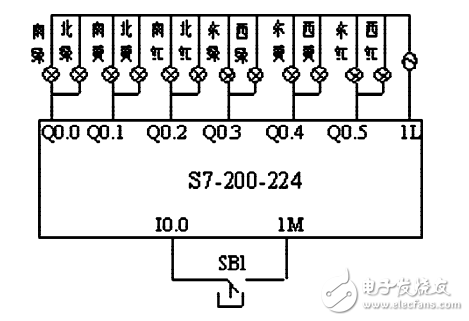
Figure 1 system input and output wiring diagram
2, hardware wiring and I / O port allocationAccording to the design requirements, the Siemens S7-200-224 PLC is used as the controller, the start button SB1, and the red, yellow and green lights are one for each of the north and south. The input and output wiring is shown in Figure 1. The start button SB1 is connected to the input relay I0.0 end, the east-west direction green light is connected to the output relay Q0.3 end, the east-west direction yellow light is connected to the output relay Q0.4 end, and the east-west direction red light is connected to the output relay Q0.5. At the end, the north-south direction green light is connected to the output relay Q0.0 terminal, the north-south direction yellow light is connected to the output relay Q0.1 terminal, the north-south direction red light is connected to the output relay Q0.2 terminal, and the output terminal power supply is connected with the output common terminal 1L.
3, system ladder designIn order to make the design idea clear and convenient, the sequential control method is adopted. Sequential control refers to the system or production equipment under the action of each input signal, the internal component status changes according to the pre-specified time sequence of the production process, so that each actuator operates automatically and orderly in the production process. The most basic design idea of ​​the PLC sequential control design method is to divide a complete working cycle of the control system into several sequential stages, which are called steps. Then, the internal programming elements representing each step are controlled by the conversion condition so that their states change in a certain time sequence, and the final output control of the corresponding actuator is divided according to the change of the input state. The state of each output does not change in any step, but the total state of the output of the two adjacent steps is different. This division of the steps represents a very simple logical relationship between the state of each step programming component and the state of each output.
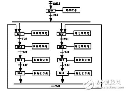
In combination with this design requirement, either a single process programming method or a dual process method can be used. In the design, the double-flow method is adopted, and the parallel branch structure is applied. The action of the east-west and north-south direction signal lights is divided into two processes at the same time, and the respective time-series actions are respectively operated, and the cooperation with each other is organically coordinated by a unified clock, There will be deviations, concise and clear, and clear ideas.

Figure 2 Ladder diagram of traffic light control system
When the PLC is powered on, the system is in the initial state S0.0 and a 1s flashing circuit is generated. SB1 presses the system to start, S0.1 and S0.5 are connected at the same time, and the east, west, and north directions work simultaneously. Now, the working principle is analyzed only in the east-west direction. The east-west green light starts to work, and the timer T37 starts to be timed 20s. After 20s, the first step is reset, the second step S0.2 is performed, the green light flashes, and the initial 1s flashing circuit is used. The timer T38 is set to 3s. Do the purpose of flashing 3 times. After 3s, the second step is reset, the third step S0.3 is performed, the east and west yellow lights work, the timer T39 is timed 2s, the second step is reset after 2s, and the fourth step S0.4 is entered, the east and west red lights start working. . At the same time, the timer T40 starts timing, and after 30 seconds, it returns to the first step, and the loop continues. The north-south direction is the same as the east-west direction and will not be described again. The ladder diagram is shown in Figure 2.
4 Conclusion There are many ways to implement the design method of traffic lights. Since traffic lights are installed at noisy traffic intersections, the requirements for stability, reliability and anti-interference of the work are high. Traditional design methods always have defects, and PLC is designed for industrial applications, which has great advantages in traffic light control systems. The PLC sequential design method is an advanced design method in the sequential control system, which is not only easy to accept, improve design efficiency, save design time, but also facilitates debugging, modification and reading of the program, and shortens the design cycle. The commissioning results of the traffic light system designed in this time meet the requirements and have certain promotion value in reality.
Shenzhen Xcool Vapor Technology Co.,Ltd , http://www.xcoolvapor.com