Schematic diagram of traffic light system: In order to ensure smooth and smooth driving of vehicles at intersections, automatic control traffic lights are often used for command. The red light (R) is on, indicating that the road is forbidden; the yellow light (Y) is on to indicate parking; the green light (G) is on to indicate permission to pass. See below:
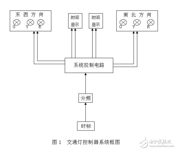
According to the 74LS164 fourteenth twisted counter state loop conversion principle. The article makes a deep and comprehensive analysis and elaboration on the design principle and design method of traffic signal logic circuit. It improves the design ability, broadens the design idea, and is familiar with the comprehensive application ability of small and medium-sized integrated circuits for designers engaged in digital electronic logic circuits. Understanding the control principle of the circuit and improving the engineering practice ability of the comprehensive application of the knowledge have important reference value.
1 traffic signal control system function designTraffic signal control system at the intersection 1.1 cross-plane layout (see Figure 1)
Note: LMG- Main Road Green Light LMY- Main Road Yellow Light LMR One Main Road Red Light
LBG trunk road green light LBY- branch road yellow light LBR- branch road red light
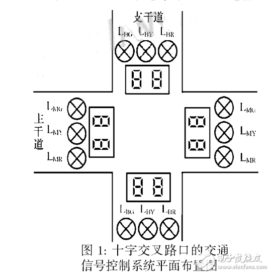
Because there are many vehicles in the main road, the release time is relatively long, the design release time is 485; the vehicles on the trunk road are less, the release time is relatively short, and the design release time is 24S; each time the green light turns red, the yellow light is required to be 4S. And intermittent flashing, at this time another thousand red light status remains unchanged, there are countdown digital display on the main road and the main road, as a time reminder, so that pedestrians and vehicles can intuitively master the transit time, digital display The change should always be in sync with the status of the signal.
2 Traffic signal logic circuit design (see Figure 3)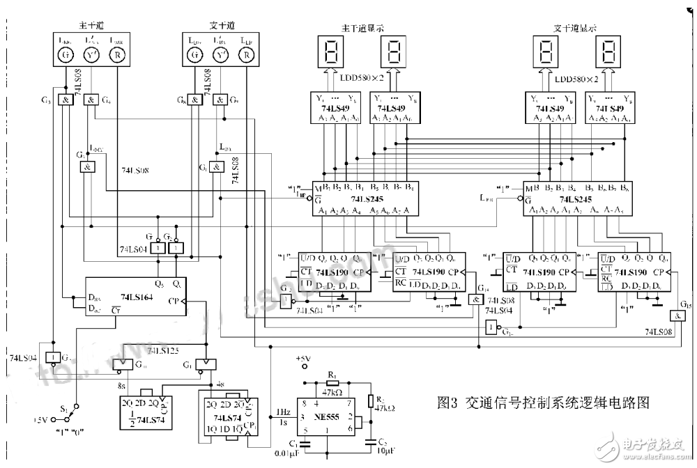
3.1 clock source
The clock source consists of the NE555 time base circuit. Standard second signal used to generate 1HZ:
3.2 Divider
The divider consists of two 74LS74s. The first 74LS74 divides the 1HZ second signal by 4 to obtain a 4S signal, and the other 74LS74 divides the 4 second signal by 2 to obtain a signal period of 8S. The signals of 4S and 85 are time-divisionally sent to the clock signal input terminal of the main controller 74LS164 for controlling the time when the signal lamp is in different states:
3.3 main controller
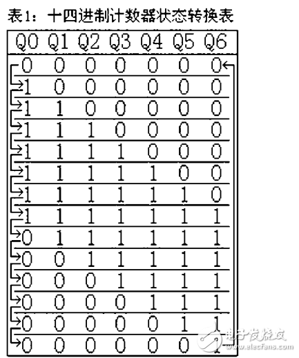
The main controller is a fourteen twisted ring counter consisting of a 74LS164. It is the core of the whole circuit. It is used to control the on and off and duration of the red, yellow and green signal lights in two directions. The state transition is shown in Table 1 under the continuous trigger of the rising edge of the clock CP.
3.4 Signal lamp decoding drive circuit design (see Figure 3)
The signal decoding driving circuit is composed of several thousand gate circuits, which is used to decode the four states of Q5Q6 in the main controller and directly drive the red, yellow and green three-color signal lamps, and the four states of the Q5Q6 in the torsion ring counter. OO, 10, 11, and 01 respectively represent the four working states of the traffic lights of the main road and the main road: the main road is green and the main road is red; the main road is yellow and the main road is red; the main road is red. The green light is on; the main red light is on, the yellow light is on, and the light is on, and the light is off, the true value table of the signal decoding drive circuit is obtained (see Table 2).
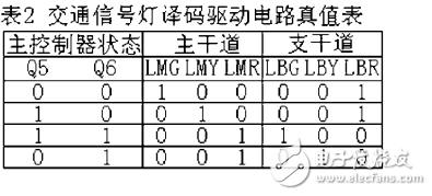
The logical expression of each signal light can be derived from the truth table: LMG=. ;LMY=Q5.;LMR=Q6 ;LBG=Q5.Q6; LBY=.06; LBR=: The yellow light should be intermittently flashed (4 times during 4 seconds), so the standard second pulse of LMY, LBY and 1S The signal CP is ANDed: LMY'=LMY.CP; LBY=LBY.CP:
3.5 signal operation timingAccording to the timing diagram, during the Q5Q6=00 period, a total of 6 CP trigger pulses are required. Therefore, the time base signal CP2 with a period of 8 seconds should be sent to the CP terminal of the ring counter. Then 6TCP2=6 x 8S=48S, which is in accordance with The green light discharge time is the same for 48 seconds. When Q5Q6 is in the three states of 10, 11, and 01, the time base signal CP1 with a period of 4 seconds should be sent to the CP end of the torsion ring counter to satisfy the three types. When the signal is on and off in the state, the above 8 seconds and 4 seconds time base signal time-sharing to the twist ring counter CP end is completed by G10, G11, G11 of 74LS04 G9, 74L.S125 (see Figure 3), only When LMG is on (48 seconds), G10 turns on G11, and the 8 second time base signal is sent to the twist ring counter CP. In the other three states, LMG is off, and Gi0 is off G11. The 4 second time base signal is sent to the twisted-loop ten-digit CP end.
3.6 Digital display control circuitThe digital display control circuit consists of two subtraction counters consisting of four 74LS190s for control of the countdown digital display. When LMG is on and LBR is on (Q5Q6=00), the 52-element subtraction counters of the two 74LS 190s corresponding to the main road start to work. Starting from the number “52â€, every second pulse, the display number is reduced by 1. When it is reduced to "0", LMR is on and LBG is on. At the same time, the 52-bit subtraction counter of the main channel stops counting, and the 28-digit subtraction counter composed of two pieces of 74LS190 starts to work from the number "28". “Begin, every second pulse, the display number is decremented by 1 until it is reduced to “0â€. The initial value before the subtraction count is realized by using the yellow light signal on the other road to control the LD end of the 74LS190. When the light is on, the subtraction circuit is set to the initial value; when the yellow light is off and the red light is on, the subtraction counter starts counting down.
3.7 Digital display circuitThe digital display circuit consists of two 74LS245 and four 74LS49 integrated circuits and four LED seven-segment digital tubes LDD580. It is used to display the number of the tenth hour, because the subtraction counters of the main road and the branch road work in a time-sharing manner, and the digital display in both directions is the same number at any time. This can be achieved by using two pieces of 74LS245. Features. When the main channel subtraction counter counts, corresponding to the 74LS245 operation of the main road, the working state of the main road counter is simultaneously sent to the decoding display circuit in two directions, and vice versa, when the branch road subtraction counter starts counting, corresponding to the branch road The 74LS245 starts working, and the working state of the branch counter is simultaneously sent to the decoding display circuit in two directions.
The release time of the main road and the main road can be set freely. For example, the release time of the main road can be set to 60 seconds, the time of the main road is 30 seconds, and the time when the yellow light flashes is 5S. The frequency coefficient can achieve this function. The standard second signal of 1HZ is divided by a rising edge triggered 5-divider to obtain a signal with a period of 5S, and after 2 minutes, a signal with a period of 10S is obtained, and the period is The 5S and 10S signals can be sent to the CP of the 74LS 164 in turn, and the 5 divider can be implemented with the 74LS290.
5 inch screen, square model & vertical model.
Dynamic temperature measurement face recognition terminal, which performs identity recognition based on the facial feature information of the person, and uses an infrared sensor to measure and record the body temperature in real time.
Applicable to office building, community, park, campus, and other public places such as access control attendance and temperature identification management.
Time Card Punch Machine,Face Recognition Terminals,Face Recognition Terminal,Infrared Temperature Instrument
Guangzhou HangDeng Tech Co. Ltd , http://www.hangdengtech.com