Micropower impact radar is a new type of high-tech radar developed in recent years in the world. As a type of ultra-wideband radar, impulse radar directly transmits a carrier-free baseband very narrow pulse. Unlike traditional radar, it is an impulse radar. The system does not need to perform carrier modulation on the transmitted signal, nor does it need to perform carrier demodulation on the received signal. Instead, it transmits and receives a very narrow pulse signal without carrier, and obtains target information through a corresponding signal processing circuit. Its outstanding features are low power, long life, low cost and wide application.
Generally, the signal transmitted by the pulse radar is a radio frequency pulse train, and the transmission signal of the impulse radar is directly an impulse pulse train. The impact radar transmits and receives ultrashort pulses to achieve distance detection. The distance resolution of the radar is proportional to the transmitted pulse width Ï„, that is, the distance resolution d=Ï„c/2, where c is the propagation speed of the electromagnetic wave in space. Usually, the impulse radar emits ultrashort pulses of the order of nanoseconds or even picoseconds, so the range resolution can be several to several tens of centimeters. But the penetration performance of radar and high-resolution imaging are a contradiction. Because this paper mainly studies the application of micropower impulse radar technology in the life detection of wall penetration, and focuses on the penetration performance of the wall, the low frequency working frequency band is selected. The micro-power short-range ultra-wideband radar can penetrate a 6 m thick brick wall with an antenna diameter of only 45 cm. The transmitter and receiver have only one radio size. Studies have shown that in the low frequency range, electromagnetic waves in the range of 1 to 10 GHz have little attenuation as they pass through the concrete wall, and as the frequency decreases, the attenuation also decreases. Therefore, frequencies below 10 GHz are suitable for wall penetration detection of bricks and concrete structures, and the lower the frequency, the better the penetration performance.
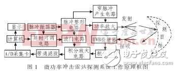
1 System working principleThe block diagram of the micro power impact radar detection system is shown in Figure 1. This system is mainly composed of a pulse transmitter, a receiver, a signal processing circuit and an antenna.
In Fig. 1, the pulse oscillator generates a pulse signal. On the one hand, the pulse is shaped as a trigger pulse, and the narrow pulse generation circuit is triggered to generate a very narrow pulse, which is transmitted through the broadband antenna, and the echo signal reflected by the target is transmitted to Receiving the sampling circuit; on the other hand, the signal generated by the pulse oscillator is used to generate a narrow pulse as a distance gate to select the received signal, receive the sampled output signal, accumulate the received signal through the integrating circuit, and then pass through the amplifying circuit and The bandpass filter circuit detects the weak target echo signal, and finally sends it to the computer for display and processing through the A/D acquisition card, and uses the digital signal processing technology to control the detection radar gate.
The system receiving signal processing circuit design is the basis of the realization of the micro power shock radar receiver. The block diagram of the structure is shown in Fig. 2, which is mainly composed of a sampling integration circuit, a variable delay unit, a band pass filter circuit and an amplification filter circuit.

2.1 Sampling integration unit
The integral sampling circuit performs correlation detection on the received UWB weak pulse signal reflected by the target and the delayed reference pulse signal, that is, sampling integration, improves the signal to noise ratio, and then implements the human body through the band pass filter circuit and the amplification filter circuit. Reception and detection of motion information and vital sign information. Here, the variable delay circuit provides an accurate synchronous reference pulse signal for the sampling integration circuit, one input of which is the transmitting end pulse signal, and the other input is precisely controlled by the program receiving the back end micro control unit.
2.2 Bandpass filter design
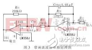
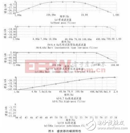
After the sampled and integrated signals are mixed with high-frequency components, it is necessary to take out the signal including the upper and lower cutoff frequencies of the human body motion of 0.05 to 10 Hz, which lays a foundation for extracting the respiratory and heartbeat signals from the receiving back end. It is necessary to design a band-pass filter with an upper and lower cutoff frequency of 0.05 to 10 Hz. The circuit principle is shown in Figure 3. It can be seen that the designed bandpass filter has a relatively flat passband at 0.05-10 Hz.
2.3 amplification filter circuit design
The amplification filter circuit can amplify and filter the front end output signal of the UWB impact radar, and provide a hardware platform for human life parameter detection and distance information detection. For the characteristics of UWB radar output signal, the design of the amplification filter circuit must pay attention to the low-frequency response of the circuit, the amplification of the weak signal by the circuit, and the DC offset of the high-magnification amplifier. In the above problem, the low frequency response of the circuit can be solved by precisely designing the parameters of the filter. If the weak signal is amplified, the amplification factor of the circuit must be high, but if the amplification factor is too large, the circuit will generate DC, which will cause the baseline to drift or produce distortion. In the circuit, a RC coupling circuit is provided to accumulate DC for each stage of the circuit. The bias voltage provides a bleeder loop.
The amplification filter circuit is based on the respiration rate range of the human body (15 to 20 times/min) and the heart rate range (50 to 100 times/min). The signal of the relevant detection circuit is divided into two paths to detect the respiratory and heartbeat signals respectively. The block diagram is shown in Figure 4. The amplifying circuit mainly comprises a preamplifier circuit, an intermediate stage amplifying circuit and a post amplifying circuit. The filter circuit mainly has low-pass filtering, high-pass filtering and band-stop filtering. It consists of a 0.6 Hz low-pass filter (CPF), a 0.7 Hz high-pass filter (HPE), and a 50 Hz notch filter (BEF).
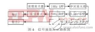
In the design of the amplifying circuit, considering the increase of the pre-stage gain, it is beneficial to improve the common-mode rejection ratio of the circuit. However, when the gain of the pre-stage is too high, when the input terminal introduces a very low-frequency signal, the front-level “zero†point drifts or is strong. When the signal is introduced, it is easy to make the latter circuit saturated and cause "blocking". Therefore, the gain design of the circuit is as follows: the preamplifier gain is 30 dB, the intermediate stage gain is 10 to 100 dB, the post amplifier gain is 30 dB, and the total gain range is 300 to 30 000 dB.
The filter circuit plays an important role in the signal pre-processor, which determines the passband of the signal and also has the effect of filtering out interference.
2.3.1 Low Pass Filter Design
The human body's respiratory rate and heart rate are less than 10 Hz, so the preamplifier output signal first filters out other interfering signals through a 10 Hz low-pass filter, and the lower 0.6 Hz low-pass filter is used to detect human respiratory signals.
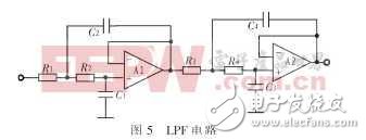
The low-pass filter circuit mainly filters out the interference signal and requires the largest flat region among the amplitude-frequency characteristics. For this purpose, a fourth-order voltage-controlled voltage source Butterworth Butter-type filter is selected. The filter characteristics of the voltage-controlled voltage source type circuit structure are that the number of components used is small and the requirements on the amplifier are not high. In this stage of the circuit, the resistor error is less than 0.01%, and the capacitor error is less than 0.1%. Since the selected resistance value in the circuit is not within the resistance sequence, in the actual circuit, multiple resistors are connected in series to obtain the required resistance value, and the capacitance in the circuit must be strictly selected. The circuit principle is shown in Figure 5. The component values ​​of the 10 Hz, 0.6 Hz fourth-order Butterworth LPF circuit are shown in Table 1.

2.3.2 0.7Hz high-pass filter circuit
A 0.7 Hz high-pass filter is used to detect the heartbeat signal. Here, a second-order high-pass filter formed by two second-order voltage-controlled high-pass filters is used to form an O.7Hz high-pass filter. The circuit is shown in Fig. 6.

2.3.3 50 Hz notch circuit
The 50 Hz notch plays an important role in the circuit. During the detection process, the DC power supply, the transmission line in the surrounding environment, etc. will generate 50 Hz power frequency interference to the signal pre-processing circuit. Therefore, it is necessary to add a 50 Hz notch filter to the circuit to filter out the 50 Hz interference signal coupled by other circuits. The circuit is shown in Figure 7. The design requirements for the 50 Hz notch are: fo=50 Hz; B≤4 Hz; Q≥10.
The circuit consists of a 50 Hz bandpass filter and an adder circuit. One pass enters the adder input via a 10kΩ resistor, and a 50 Hz bandpass filter with a gain of -1 is coupled into the adder input via a 10 kΩ resistor. The two signals are added together to obtain a 50 Hz notch.
3 test resultsAccording to the previous design circuit, the components in the 0.05~1O Hz bandpass filter, the 10 Hz and 0.6 Hz low-pass filters, the 0.7 Hz high-pass filter and the 50 Hz notch circuit are evaluated and passed through MulTIsim. Simulation and repeated debugging, and through the circuit test, obtained the ideal amplitude-frequency characteristics, the amplitude-frequency characteristics of each part of the circuit test results shown in Figure 8. As can be seen from Figure 8, the 0.05 to 10 Hz bandpass filter, the 10 Hz and 0.6 Hz low-pass filters, and the 0.7 Hz high-pass filter all have a flat 3 dB passband and a Q Hz of the 50 Hz notch. More than 5.
In this paper, a receiving signal processing circuit for micro-power shock radar system is designed. The design principle of each sub-module circuit and the simulation debugging results of the main modules are given. The simulation results show that the main circuit, namely band-pass filter and amplification filter The amplitude-frequency characteristics are ideal. The circuit designed according to this simulation result has been tested to achieve the theoretical design requirements. The circuit fabricated according to the design has the characteristics of simple structure, low cost and good performance, and has certain practical value in the ultra-wideband technology.
Bilge float alarm,Bilge float alarm price,Bottom floating alarm
Taizhou Jiabo Instrument Technology Co., Ltd. , https://www.taizhoujiabo.com