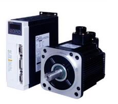
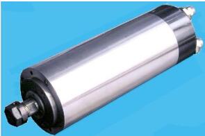
This article mainly explains the spindle servo system. Firstly, it introduces the function of the spindle servo. Secondly, it introduces the fault representation of the spindle servo system. Finally, it explains the fault diagnosis method of the spindle servo system.
The main role of spindle servo1ã€Control servo motor
2, can be oriented, low speed torque, rigid tapping
Fault representation of spindle servo system1. Display alarm information or alarm content on the CRT or operation panel;
2. The failure of the spindle drive is displayed on the spindle drive using a warning light.
3, spindle work is not normal, but without any alarm information, spindle servo system common faults are:

1, external interference
Due to electromagnetic interference, poor shielding and grounding measures, the spindle speed command signal or feedback signal is disturbed, causing spindle drive to randomly and irregularly fluctuate. The method of distinguishing whether there is interference or not is: when the spindle speed command is zero, the spindle will still reciprocate, and adjusting the zero speed balance and drift compensation will not eliminate the fault.
2, overload
Excessive cutting amount, frequent positive, reverse, etc. can cause overload alarm. The specific performance of the spindle motor overheating, spindle drive system display over-current alarm.
3, spindle positioning jitter
Spindle accurate stop for tool exchange, fine retraction and gear shifting, etc., there are three ways to achieve:
(1) Mechanical quasi-stop control
(2) Electrical quasi-stop control of magnetic sensor
(3) Encoder-type accurate stop control
4, spindle speed and feed does not match
When performing thread cutting or cutting with the feed command per revolution, there will be a failure to stop feeding and the spindle will continue to run. To execute a command for feed per revolution, the spindle must have a feedback signal for each revolution of the spindle. Normally, there is a problem with the spindle encoder.
It can be determined in the following ways:
1. CRT screen has alarm display.
2. Call the machine data or I/O status via the CRT to observe the signal status of the encoder.
3. Execute the program with a feed instruction per minute instead of feed per revolution and observe if the fault disappears.

5, speed deviation from the command value
When the spindle speed exceeds the range specified by the technical requirements, consider:
1) The motor is overloaded.
2) The spindle speed analog output (usually 0 - +-10V) output by the CNC system does not reach the value corresponding to the speed command.
3) The speed measuring device is faulty or the speed feedback signal is disconnected.
4) Failure of the spindle drive.
6. Spindle abnormal noise and vibration
First, it is necessary to distinguish whether abnormal noise and vibration occur in the mechanical part of the spindle or the electric drive part.
1) In the deceleration process, it is generally caused by another driving device, such as the failure of the regeneration circuit in the AC drive.
2) Generated at constant rotation speed, can be distinguished by observing whether there is noise and vibration in the process of free stop of the spindle motor. If there is, the mechanical part of the spindle has problems.
3) Check whether the vibration period is related to the rotation speed. If irrelevant, the spindle drive is generally not adjusted; if it is relevant, check whether the mechanical part of the spindle is good or not.
7, spindle motor does not turn
From the CNC system to the spindle drive, in addition to the speed analog control signal, there is an enable control signal, which is typically a DC+24V relay coil voltage.
1) Check whether the CNC system has a speed control signal output.
2) Check to see if the signal is on. Observe the I/O status through CRT and analyze the plc graphic (or flow chart) of the machine tool to determine whether the spindle start conditions, such as lubrication and cooling, are satisfied.
3) Failure of the spindle drive.
4) Spindle motor failure.

Solar Cable,Solar Wire,Pv Cable,Solar Panel Cable
Sowell Electric CO., LTD. , https://www.sowellsolar.com