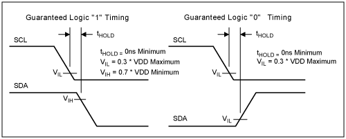
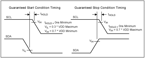
Preface This application note details the difference between the DS1624's 2-wire timing and I²C. In I²C, the SDA signal is delayed by at least 300ns inside the slave, thus allowing simultaneous changes in SCL and SDA levels. However, the DS1624 does not delay the SDA signal for the SCL signal, so the bus master must maintain the SDA signal in the correct logic state before the SCL transitions to a logic low level to prevent false triggering of START and STOP operations. Correct timing The SDA line of the DS1624 does not have an internal delay for SCL. Therefore, when writing data, the SDA logic level must be maintained outside the DS1624 before SCL transitions to a low level. Otherwise, it will be mistaken for a start or stop signal. When writing a logic "1" on a 2-wire bus, it is necessary to ensure that the SCL level is lower than the logic low threshold level VIL before the SDA level drops to a safe logic high threshold level VIH (0.7 x VDD minimum) (0.3 x VDD maximum). When writing logic "0", the SCL level must be lower than VIL before the SDA level rises to VIL. When the START signal is generated, SDA must be below VIL before SCL drops to VIH. When the STOP signal is generated, SDA must be higher than VIH before SCL is reduced to VIH. The VIL and VIH values ​​of each device have been tested in production. To ensure that the entire voltage and temperature range, even if there are device manufacturing tolerances, this timing can run correctly.

figure 1.

Figure 2. Summary The timing of the DS1624 is somewhat different from the I²C standard. DS1624 does not delay SDA internally for SCL. Therefore, the system host is required to maintain the SDA level on the falling edge of SCL to prevent the logic "1" from being mistaken for the START signal and the logic "0" to be mistaken for the STOP signal.
By running the grating ruler, the grating bars shield the light source, the light is transmitted between the grating bars and the bars, from which the number of pulses output by the receiver, a certain number of pulses are preset by the encoder, and when the number of output pulses reaches the preset value Just generate a control signal for the actuator to act. This method is generally used in CNC automatic control.
Encipheror Optical Grating,No Burr Encoder Raster,Stainless Optical Grating
SHAOXING HUALI ELECTRONICS CO., LTD. , https://www.cnsxhuali.com