Abstract: High-precision sinusoidal signals are often required in electronic and communication products. Traditional sinusoidal signal generators tend to have low frequency stability and accuracy at low-frequency output. This article introduces MicroLinear's single-chip sinusoidal signal generator chip ML2035, which can generate sinusoidal signals from DC to 25kHz without the need for other peripheral devices, and uses this chip to complete a simple sinusoidal signal generator circuit. the design of.
Keywords: signal generator, signal source, sinusoidal signal, ML2035, DDS
The sinusoidal signal source is a widely used signal source, and its requirements are also increasing with the development of technology. Conventional sinusoidal signal generators tend to have low levels of stability and accuracy at low frequency output. We know that in order to obtain a signal source with high frequency stability, it is often implemented by a phase-locked loop, but this method is complicated and bulky. In recent years, DDS technology has been widely used in electronic measurement, radar systems, FM communication, electronic countermeasures, etc. due to its easy to generate fast frequency conversion, high resolution, and phase controllable signals. However, if a low-frequency sinusoidal signal generator is developed using the usual Analog series DDS chip, an external microprocessor is often required, so the circuit is complicated and the frequency stability is not good. To this end, this article will discuss a simple sinusoidal signal generator based on ML2035 design, which has fewer peripheral components, simple circuit implementation, and can not require the characteristics of an external microprocessor.
The ML2035 is a monolithic sinusoidal signal generation chip from MicroLinear that produces a sinusoidal signal from DC to 25 kHz with almost no external components required, and its output sinusoidal signal frequency can be 16 bits of serial bits. Word control. Therefore, the ML2035 can be widely applied to fields such as wireless communication or modulation and demodulation which require a low-cost, high-precision sinusoidal signal generator. The main features of the ML2035 are as follows:
â— output sinusoidal signal frequency is DC to 25kHz;
â— With low gain error and low harmonic distortion performance;
â— It has a 3-wire SPI compatible serial microprocessor interface and has a data latch function;
â— Fully integrated solution functionality without the need for peripherals;
â— The frequency resolution can reach 1.5Hz (when the input clock frequency is);
â—Own internal crystal oscillator;
â— With synchronous and asynchronous data loading.
Sinusoidal Signal Generation The basic principle of the ML2035 is the same as that of the DDS. It consists mainly of sinusoidal signal generation, crystal oscillator and serial digital interface. However, the peripheral circuit of the ML2035 is simple and it has only 8 pins. The basic principle of the ML2035's programmable frequency generator is identical to that of the Direct Frequency Synthesizer (DDS). We know that DDS chips generally consist of a frequency control word, a phase accumulator, a sine look-up table, a D/A converter, and a low-pass filter. The core component of the DDS chip is the phase accumulator, which consists of an N-bit adder and an N-bit phase register, which is similar to a simple counter. For each clock pulse, the output of the phase register is incremented by a step increment value. The adder adds the frequency control data to the accumulated phase data output from the accumulation register, and sends the addition result to the data input of the accumulation register. . The phase accumulator enters the linear phase accumulation. When accumulating to full scale, a count overflow occurs. This overflow frequency is the output frequency of the DDS. The sinusoidal look-up table is a programmable read-only memory (PROM) that stores the sampled encoded value of a periodic sinusoidal signal with a phase address, containing digital amplitude information of a periodic sine wave, each address corresponding to a sine wave: A phase point of the range. The data obtained by adding the output of the phase register and the phase control word is used as an address to address the sinusoidal lookup table. The lookup table maps the input address phase information into a sine wave amplitude signal, drives the DAC, and outputs an analog signal; low pass filtering The device smoothes and filters out unwanted sample components to output a spectrally pure sine wave signal.
Since the control word length of the ML2035 is 16 bits, it is not difficult to derive the output frequency relationship of the ML2035 according to the principle of DDS.
This article refers to the address: http://

(1)
Accordingly, the frequency resolution (also the minimum frequency) of the ML2035 is

(2)
The control of the serial digital interface ML2035 can be realized by the serial digital interface of the chip, and the digital interface part is mainly composed of a shift register and a data latch. The 16-bit data word on the SID pin is clocked into the 16-bit shift register on the rising edge of clock SCK. It should be noted that the lowest position should be sent first and the highest position should be sent last. Then, under the falling edge of LAI, the data sent to the shift register is latched into the data latch. To ensure efficient latching of the data, the falling edge of the LAI should occur during the SCI "low" level. Similarly, the LAI should remain "low" during the SID data shift into the shift register.
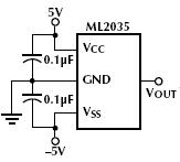
The power supply mode ML2035 has a power "sleep" function, which can effectively improve the efficiency of power supply, which is extremely advantageous for portable products. When the ML2035 is expected to remain "sleep", all "0"s can be input to the shift register and "1" can be loaded to the LATI to remain high. In this case, the power consumption of the ML2035 can be reduced to below 11.5mW, and the amplitude of the output sinusoidal signal is reduced to 0V. It should be mentioned that the power supply decoupling process should be performed on the power input of the ML2035 in the circuit design. The power supply decoupling scheme shown in Figure 1 can be used in the circuit design.

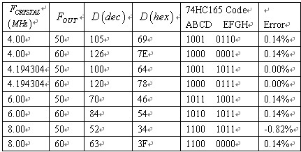
Figure 1 ML2035 power supply decoupling processing method Simple sinusoidal signal generator design The basic principle of DDS can be known, due to the limited frequency resolution of the ML2035, the output sinusoidal signal will be subject to error. For different reference clocks, different degrees of frequency error will be generated. Table 1 shows the frequency control word and frequency error of the ML2035 under common crystal oscillators.

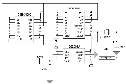
Table 1 ML2035 required frequency control word and frequency error when using common standard crystal oscillator This paper intends to use ML2035 to design a simple high-frequency frequency-free sinusoidal signal generator with frequency of 1000Hz, because the crystal oscillator is lower than 3.5MHz. High and bulky, so choose 6.5536 crystal oscillator here. It can be known from equation (1) that the required frequency control word is 1280, so the required 16 bits control bit is 1111D101000000000, so that the frequency error of the output sinusoidal signal will theoretically reach 0.00%. Figure 2 shows the circuit schematic of the simple sinusoidal signal generator. The 74HC4060 counter functions as an oscillator and a timer, while the 74HC4002 is a high-speed CMOS quad NAND device. In order to achieve an output sinusoidal signal frequency of 1000 Hz for the ML2035, the first 8 pulses must be shifted into 8 bits 0, and then the next 8 pulses are shifted into 11111010.

Figure 2 is based on ML2035 1000Hz sinusoidal signal generator circuit schematic diagram Conclusion Because the traditional sinusoidal signal generator often low frequency output frequency stability and accuracy indicators are not high, if you choose to use the DDS series chip developed by Analog Low-frequency sinusoidal signal generators often lead to problems such as complicated circuits and large size. To this end, this paper discusses a simple sinusoidal signal generator based on ML2035 with an output frequency of 1000Hz, and is intended to be applied to a radar device. Because it has fewer peripheral components, the circuit is simple to implement and does not require the characteristics of an external microprocessor. Therefore, the ML2035 can be widely used to generate sinusoidal signals with low price and high precision.
High voltage
Resistor dividers (RFD Series)
are suited for all the fields of high voltage and small signal multiply. Such as
Such as High voltage power
supply, Medical electronical devices,
Audiophile speakers, Audio systems, Smoke sensors, Infrared detectors, Radiation detectors, Special gas detectors
High Voltage Polyester Capacitor,High Voltage Divider,Flat High Voltage Divider,High Voltage Resistor Dividers,High Power Resistor
XIAN STATE ELECTRONICS TECHNOLOGY CORP. , https://www.shvcomponents.com