Basic electrical load of automotive electronics
Through the following electrical load, you can understand the electronic environment (12V system) facing automotive electronics.
Overvoltage experiment
18V experiment: Simulate the failure of the generator regulator, causing the generator output voltage to rise, which is higher than the normal voltage. In our experiment, the module temperature was 20 degrees lower than the maximum temperature of the module, and the applied voltage was 18V for a duration of 60 minutes.
24V experiment: simulate the situation of auxiliary starting. In our experiment, the module temperature was at room temperature, and a voltage of 24V was applied for a duration of 60 seconds.
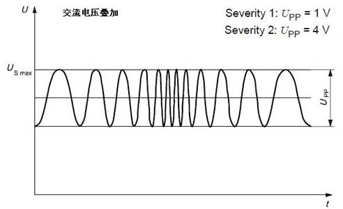
Superimposed AC voltage experiment
Simulate the alternating current left in the DC power supply (distribution system).
Experimental conditions: Upp = 1 V, 4V two levels; the internal resistance of the power supply is 50 mΩ ~ 100 mΩ; the waveform frequency range is 50 Hz ~ 20 KHz; the sweep waveform type is triangular or logarithmic; the sweep duration is 120 s ; Sweep frequency is 5 times.
Slow voltage drop and rise
Simulate the gradual discharge and charge of the battery. Apply voltage to the module at a rate of 0.5 ± 0.1 V / min, reduce the supply voltage from USmax to 0 V, and then increase from 0 V to USmax.
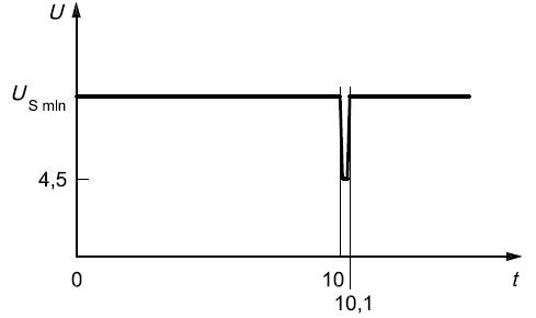
Power supply voltage interrupted
Instantaneous supply voltage drop: Simulate the effects of typical fuses in other circuits when blown. Note that the rise and fall time of the test pulse is ≤10 ms.
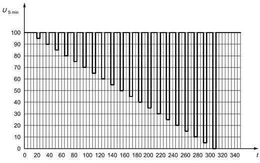
Voltage sag reset performance: When the voltage sag is checked, the reset performance of the module is applicable to devices with a reset function. The supply voltage is reduced from USmin to 0.95 USmin at a rate of 5%, held for 5 s, and then increased to USmin, held for at least 10 s and tested for function. Then reduce the voltage to 0.9 USmin, etc., continue with a 5% gradient of USmin until it drops to 0V, and then increase the voltage to USmin.
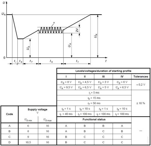
Module startup characteristics: Check the characteristics of the DUT at startup and after startup.
Reverse voltage: When using the auxiliary starting device, the module's resistance to the reverse connection of the battery. Apply a reverse voltage of 14V to all relevant input terminals of the module for 60 seconds.
Ground offset: If the module has two or more power supply lines, verify the reliable operation of the module. (The reference point of the module's power ground and the module's input signal ground may not be the same).
Open circuit test
Single-wire disconnection: Circuit conditions where the analog module is disconnected. Open circuit time: 10 s ± 10%; open circuit impedance: ≥ 10MΩ.
Multi-wire disconnection: When the module suffers from abrupt disconnection of multiple lines, the functional state can reach the specified requirements. Open circuit time: 10 s ± 10%; open circuit impedance: ≥ 10MΩ. For multi-connector devices, each possible connection should be tested.
Short circuit protection: The short circuit of the input and output circuits of the analog device.
Signal circuit: all relevant input and output terminals of the module are connected to USmax and ground in turn for 60 seconds.
Load circuit: The module is connected to the power supply and the load circuit is in working condition. All electronic protection output terminals should ensure that they can withstand the short-circuit current and return to normal operation after the short-circuit current is cut off. All typical fuse protection output terminals should ensure that they can withstand the short-circuit current and return to normal operation after replacing the fuse. The unprotected output can be damaged by the test current.
(Insulation) Withstand voltage: to ensure the dielectric withstand voltage capability of the dielectric. Overvoltages cause leakage currents between module components through the electric field, which may negatively affect the insulation performance. (Inspect the ability of insulating materials to withstand high voltages caused by disconnecting inductive loads).
Insulation resistance: The minimum impedance necessary to ensure the current between the insulated circuit of the module and the conductive parts is used to check the insulation properties of the system and materials.
Rain Test Chamber,Tightness Testing Test Box,Waterproof Rating Test Chamber,Environmental Test Chamber
Wuxi Juxingyao Trading Co., Ltd , https://www.juxingyao.com