Space-division multiplexing (SDM) MIMO processing can significantly improve the spectral efficiency, thereby greatly increasing the capacity of wireless communication systems. The space division multiplexing MIMO communication system, as a means to greatly increase the capacity and connection reliability of wireless systems, has recently attracted widespread attention.
The best hard decision detection method for MIMO wireless systems is the maximum likelihood (ML) detector. ML detection is very popular because of its excellent bit error rate (BER) performance. However, the complexity of direct implementation will increase exponentially with the increase in antennas and modulation schemes, making ASICs or FPGAs only available for low-density modulation schemes that use a small number of antennas.
In MIMO detection, an excellent method that can not only maintain BER performance comparable to the best ML detection, but also greatly reduce the computational complexity, is non-spherical detection. This method can not only reduce the detection complexity of SDM and space division multiple access systems, but also maintain BER performance comparable to the best ML detection. There are many ways to implement a spherical detector, and each method has many different algorithms, so designers can seek the best balance between multiple performance indicators such as wireless channel throughput, BER, and implementation complexity.
Although algorithms (such as K-best or depth-first search) and hardware architecture obviously have a great impact on the final BER of the MIMO detector, the channel matrix pre-processing generally performed before spherical detection will also have a final impact on the MIMO detector. BER performance has a huge impact. The channel matrix preprocessing can be complicated and simple. For example, based on the variance calculation result (variance computaTIon) of the channel matrix, the priority of processing the space division multiplexed data stream can be calculated. You can also use a very complex matrix factorization method to determine Priority for ideal (measured by BER) data stream processing.
Signum Concepts is a San Diego-based communications system development company that has been working closely with Xilinx and Rice University to design MIMO for space-division multiplexing MIMO for 802.16e broadband wireless systems using FPGAs. Detector. The processor uses a channel matrix preprocessor to implement a continuous interference cancellation technology similar to the Bell Labs layered space-time (BLAST) structure, and finally achieves near-maximum likelihood performance.
System considerations
Ideally, the detection process requires ML solution calculation for all possible symbol vector combinations. The spherical detector is designed to reduce the computational complexity by using simple arithmetic operations, while still maintaining the numerical integrity of the final result. The first step of our method is to decompose the complex numerical channel matrix into expressions with only real numbers. This operation increases the matrix dimension, but simplifies the calculation of processing matrix elements. The second aspect of reducing computational complexity is the reduction of optional symbols for analysis and processing of the detection scheme. Among them, QR decomposition of the channel matrix is ​​a crucial step.
Figure 1 shows how to perform the mathematical conversion to obtain the final expression of the calculation part of the Euclidean distance metric. Euclidean distance measurement is the basis of the spherical detection process. R represents a triangular matrix, and it is used to process the optional symbols starting with matrix elements rM, M. Where M represents the dimension of the channel matrix expressed in real numbers. This solution defines the traversal tree structure through M iterations, each layer i of the tree corresponds to the processing symbol of the ith antenna.

Figure 1. Partial Euclidean distance metric equation for MIMO detection of spherical detector
The order in which the spherical detector processes the antenna has a great influence on BER performance. Therefore, before performing spherical detection, our design uses a channel reordering technology similar to V-BLAST technology.
There are several options for implementing tree traversal. In our implementation, the breadth-first search method is used because it uses a popular feed-forward structure and is therefore hardware-friendly. At each layer, the implementation only selects K surviving nodes with the smallest distance to calculate the expansion.
The order in which the spherical detector processes the antenna has a great influence on BER performance. Therefore, before performing spherical detection, our design uses a channel reordering technology similar to V-BLAST technology.
This method calculates the row norm of the pseudo-inverse matrix of the channel matrix through multiple iterations, and then determines the optimal column detection order of the channel matrix. According to the number of iterations, this method can select the row with the largest or smallest norm. The inverse matrix row with the smallest Euclidean norm indicates that the antenna has the strongest influence, and the row with the largest Euclidean norm indicates that the antenna has the weakest influence. This novel method processes the weakest data stream first, and then iteratively processes data streams with high to low power in turn.
FPGA hardware application
To implement the above system, we used Xilinx Virtex®-5 FPGA technology. This design flow uses Xilinx System Generator for design capture, simulation, and verification. To support a variety of different numbers of antennas / users and modulation sequences, we designed the detector for the most demanding 4x4, 64-QAM situations.
Our model assumes that the receiver knows the channel matrix very well, which can be achieved by traditional channel estimation methods. After channel reordering and QR decomposition, we started to use spherical detectors. In preparation for using soft input and soft output channel decoders (such as turbo decoders), we generate soft outputs by calculating the log-likelihood ratio (LLR) of the detected bits.
The main architectural elements of the system include data sub-carrier processing and system sub-module management functions, in order to process the required number of sub-carriers in real time, while minimizing processing delay. The channel matrix is ​​estimated for each data subcarrier, limiting the processing time available for each channel matrix. For the selected FPGA, the target clock frequency is 225MHz, the communication bandwidth is 5MHz (equivalent to 360 data subcarriers in the WiMAX system), and the number of available processing clock cycles per channel matrix interval is 64.
We use the superb pipeline and time division multiplexing (TDM) function of the hardware function unit to meet the real-time requirements of WiMAX OFDM symbols.
In addition to the high data rate, controlling the submodule delay during the architectural design guidance process is also an important issue. We solved the delay problem by introducing continuous channel matrix TDM. This method can extend the processing time between the elements of the same channel matrix while maintaining a high data throughput. The number of channels that make up the TDM group varies with different sub-modules. In the TDM scheme, the channel matrix inversion process uses 5 channels, and 15 channels are time-division multiplexed in the real QR decomposition module. Figure 2 is a high-level flowchart of the system.
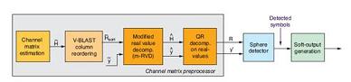
Figure 2. High-level flowchart of a MIMO 802.16e broadband wireless receiver
Channel matrix preprocessing
The channel matrix preprocessor determines the optimal detection order of each layer of the space division multiplexed composite signal. The preprocessor is responsible for calculating the pseudo-inverse matrix norms of the channel matrix, and according to these norms, the next transport stream to be processed is selected. The row with the smallest norm in the pseudo-inverse matrix corresponds to the strongest transport stream (minimum noise amplification after detection), and the row with the largest norm corresponds to the worst quality layer (maximum noise amplification after detection). Our embodiment first detects the weakest layer, and then detects each layer in the order of lowest noise amplification to highest noise amplification. For each step in the sorting process, the corresponding column in the channel matrix is ​​then cleared, and then the simplified matrix enters the next-level antenna sorting processing pipeline.
In the preprocessing algorithm, the calculation requirements of the pseudo-inverse matrix are the highest. The core of this process is matrix inversion, which is usually achieved by QR decomposition (QRD) through Givens rotation. Commonly used angle estimation and plane rotation algorithms (such as CORDIC) will cause serious system delay, which is unacceptable for our system. Therefore, our goal is to use FPGA's embedded DSP resources (such as the DSP48E in Virtex-5 devices) to find alternative solutions for vector rotation and phase estimation.
The pulsating array structure of QRD consists of two types of processing units-diagonal units or boundary units and non-diagonal units or internal units. The boundary element performs a vector function to generate the rotation angle used by the elements within the array. To get the desired rotation angle, you can multiply the value in the non-diagonal element by the conjugate complex number in the diagonal element, and then divide by the reciprocal of the complex number. The division is actually done by multiplication, that is, when the function is observed to be nearly linear, it is multiplied by the reciprocal calculated according to the polynomial approximation of the defined interval. Figure 3 shows the signal flow diagram of using this approximation to complete this complex rotation in a diagonal pulsation unit.
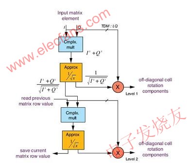
Figure 3. Diagonal pulsation unit structure diagram
The data sent to the non-diagonal elements is the result of dividing the in-phase and quadrature parts of the rotation vector by the corresponding approximate values. Not only did we achieve high data throughput by adopting pipeline architecture for the diagonal and non-diagonal units, but we also controlled the approximation module and complex multiplier caused by time-division multiplexing of hardware across 5 channels Delay.
For the 4x4 matrix, we used 1 diagonal element and 7 non-diagonal elements. The processing time for decomposing a single matrix is ​​4x4 = 16 data cycles, and the speed of the design to deliver data is one sample every three clock cycles, so the total time for decomposing a single matrix is ​​3x4x4 = 48 clock cycles (low For the available 64 clock cycles). We used the back subsTItuTIon method on the decomposed matrix, and further performed the reordering operation in the same TDM manner.
Spherical detector
The spherical detector uses a PED unit for norm calculation. According to the tree level, we use three different types of PED units. The root node PED module is responsible for calculating all possible PEDs. The second-level PED module calculates 8 possible PEDs for the 8 surviving paths calculated by the previous level. In this way, we have 64 generated PEDs in the next level of the tree. The third type of PED module is used at other tree levels and is responsible for calculating the nearest node PED of all PEDs calculated by the previous level.
The pipeline architecture of the spherical detector (SD) can process data in every clock cycle. The result is that only one PED module is required for each level of the tree. Therefore, for a 4x4 64-QAM system, the total number of PED units is 8, which is equal to the number of trees.
SD can use two types of decoding technologies, hard decoding and soft decoding. Hard decoding can measure the order using the minimum distance matrix that runs through the various levels of the tree; soft decoding uses log-likelihood ratio to represent each bit of the output. The log-likelihood ratio is generally provided as a priority input value to a channel decoder, such as a turbo decoder.
FPGA resource occupation
Implementation and simulation include the detection process shown in Figure 2, but do not include the soft output generation module. The target chip is Virtex-5 XC5VFX130T-2FF1738 FPGA. The designed clock frequency is 225MHz, and the available data rate is 83.965Mb / s.
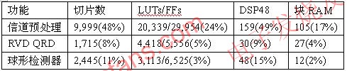
Table 1 shows the resource occupancy of each major functional unit in the design. Utilization rate (%) represents the percentage of FPGA area to the total area of ​​the XC5VFX130T device.
Table 1. Resource occupancy by subsystem
System Generator and model-based design
We used Xilinx System Generator for DSP design flow to implement a complete hard-judge chain. The design verification work not only uses the simulation semantics of MATLAB® / Simulink® environment, but also the co-simulation function of System Generator. The in-phase and quadrature parts of the channel matrix parameters are derived from the normal distribution and delivered by MATLAB to the System Generator modeling environment. We also use this simulation framework to calculate the bit error rate. Figure 4 compares our fixed-point hard decision design BER curve, floating-point hard decision design BER curve and the best ML reference curve. We developed a hardware demonstration of the design by performing hardware-based Ethernet co-simulation of the Xilinx ML510 development platform. The channel matrix parameters are sent to the spherical detector using Xilinx AWGN IP core. We calculate the BER by embedding the design into the self-synchronous BER tester. The instrument can send input to the detector and capture errors.
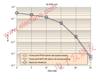
Figure 4. 4x4 64-QAM floating-point MATLAB simulation (hard decision), System Generator design (hard decision) BER curve compared to the maximum likelihood curve
This article briefly introduces the spherical detector used in the space division multiplexing MIMO communication system. We discussed in detail the architecture of the spherical detector and the channel matrix preprocessor. There are many ways to implement preprocessing. Although our method is a bit more complicated in calculation, the BER performance obtained is close to the maximum likelihood. Although our discussion revolves around WiMAX, designers can apply many of these methods to 3G LTE (Long Term Evolution) wireless systems.
Lamp Holder,Bulb Holder,Light Holder,Lamp Socket
WENZHOU TENGCAI ELECTRIC CO.,LTD , https://www.tengcaielectric.com