Based on the interface between DSP processor TMS320F2812 and SD card, a portable physiological signal data acquisition system is designed for the collection of large-capacity multi-parameter human physiological parameters. The TMS320F2812 is used as the main control chip, and the SD card is used as the main storage medium to realize real-time data collection and storage. An optimized file system is designed according to the FAT32 file system specification, and the data collected in real time can be quickly saved in the SD card in the form of text. Experiments show that the system is simple to operate and easy to carry in actual measurement, and can be used for real-time monitoring of human physiological parameters.
Physiological signals are basic parameters that characterize human life characteristics, such as blood pressure, pulse rate, and body temperature, which are important physiological signals of the human body. These signals contain useful pathological information. By analyzing these signals, it is possible to diagnose diseases in various parts of the body. Multi-parameter physiological signal data acquisition requires a large amount of data storage. Using wireless, USB and host computer communication to store data can solve this need. However, these solutions require the host computer to store data, which is not conducive to portable operations.
The SD card (Secure Digital Card) has the advantages of small size, light weight, large capacity, fast data transmission rate, great mobility flexibility and good security. It is very suitable for measurement systems that store large amounts of data for a long time. . Therefore, using SD card as a storage medium for physiological signal data acquisition system is a good solution.
This paper designs a portable physiological signal data acquisition system. The power management module is designed on the hardware to solve the different voltage requirements of each module in the system. At the same time, the DSP processor TMS320F2812 with fast processing speed is used as the main control chip, which makes the performance of collecting data and processing data more superior. The optimized FAT32 file system is designed on the software to make the write data of the large-capacity SD card faster.
1 overall design
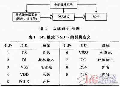
The acquisition system designed in this paper is mainly composed of power management module, SD card, TMS320F2812, etc., which fully reflects the portable design. The system design block diagram is shown in Figure 1. The system uses dry batteries as the power source, and supplies power to each module of the system through the power management module. The TMS320F2812 uses the on-chip 12-bit A/D to sample and transform the analog signals collected by the sensor, and the results are stored in the SD card. The FAT32 file system embedded in the large-capacity SD card can save the data in text format, which is convenient for data processing and waveform analysis on the host computer.
This article refers to the address: http://
2 DSP and SD card interface circuit design
According to the communication protocol of the SD card, the main controller and the SD card have two communication modes: SD mode and SPI mode. The former is fast (4-bit parallel data bus), using all signal lines; the latter is slow (data is transmitted in a single line), but it is easy to use, compatible, and easy to communicate with the main controller. The transmission speed of SPI mode can meet the system requirements designed in this paper. Therefore, this design adopts SPI mode. Table 1 shows the pin definitions of the SD card in SPI mode.
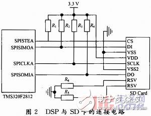
The SD card is connected to the four I/O ports of the DSP. The CS pin of the SD card is connected to the SPISTEA pin of the DSP and used as a normal I/O function. Its high and low level controls whether the SD card is enabled or not; the DI pin is connected to the SPISIMOA pin, and the DSP passes this pin to The SD card sends data and commands; the DO pin is connected to the SPISOMIA pin, and the DSP reads the data in the SD card through this pin; the SCLK pin is connected to the SPICLKA pin, and the DSP sends a clock signal to the SD card through this pin. The specific connection circuit is shown in Figure 2.
3 SD card software design
The SD card works in SPI mode, and the main controller sends commands and data to the SD card and receives the response of the SD card. The enabled SD card always responds to commands from the host controller. When an error occurs on the SD card, an error response is returned instead of the expected data.
3.1 SD card initialization
Before reading and writing to the SD card, the SD card should be initialized first. The SD card initialization process is shown in Figure 3. In order to maintain the compatibility of the SD card, the clock frequency of the SPI is set in the range of 100 to 400 kHz. After the SD card is powered on, the host must send at least 74 clock cycles to the SD card, and CS is at a low level to complete the SD card power-on process. After the SD card is powered on, it enters the SD mode by default. In this mode, it sends a reset command (CMD0) to the SD card and keeps CS low. If the response signal is 01H, the SD card enters the SPI mode.
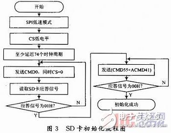
After the SD card enters the SPI mode, the host can continuously send a command (CMD55+ACMD41) to the SD card and read the response signal. If the response signal is 00H, it indicates that the SD card has completed initialization. After the initialization is completed, the SPI clock frequency needs to be set to the high-speed mode. In this mode, the high-speed read and write of the SD card can be guaranteed.
3.2 SD card read and write operations
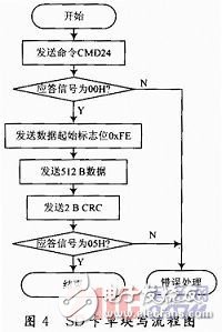
The SD card supports single block write operations (CMD24) and multiple block write operations (CMD25). Figure 4 is a flow chart of a single block write operation with a data length of 512 B. When performing a single block write operation, the host sends a write data block command (CMD24), waits for the SD card's response signal to be 00H, then transmits the data start flag 0xFE, and then sends 512 B data and 2 B (2RC check). When the response signal of the SD card is 0x05, it indicates that the SD card has correctly written the data. When the SD card is written, the output port of the SD card is low, and when the output port goes high, the write operation is completed. .
The SD card also supports single block (CMD17) and multiple block (CMD18) read operations. The data length of a single block read operation is also 512 B, and the operation flow is similar to the write operation. In operation, the read data block command (CMD17) is first sent to the SD card, and after receiving the response signal 0xFE, the 512 B data block and the 2 B CRC check are received.
4 FAT32 file system design
4.1 Structure of the FAT32 file system
In order to more intuitively view the data in the SD card, and interactive data operation with the computer. This article uses the FAT32 file system, which not only implements file operations on large-capacity SD cards, but also reads and writes files quickly.
The basic structure of the FAT32 file system on the SD card includes the following parts: a partition boot record DBR (Dos Boot Record), a file allocation table FAT (File AllocaTIon Table) data area.
Partition boot record DBR, usually including jump instructions, manufacturer identification and DOS version number, BPB (BIOS Parameter Block) and. BIOS bootloader. The BPB records the basic information of the SD card of each sector, the number of sectors per cluster, and the total number of sectors. This information is the basis for the correct operation of the SD card.
The FAT32 file system has two file allocation tables FAT1 and FAT2. FAT2 is a backup of FAT1, which records the link relationship between the cluster and the cluster.
FAT32 differs from FAT12 and FAT16 in that it does not have a dedicated root directory area, and the root directory area is merged with the data area.
4.2 Implementation of FAT32 file system
4.2.1 Initialization of the FAT32 file system
For the correct operation of the SD card, it is necessary to initialize the information structure variable of the card, such as the number of bytes per sector, the number of sectors per cluster, the number of FAT tables, and the like.
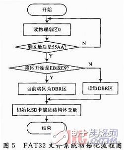
The initialization process is shown in Figure 5. First read the physical sector 0 of the card and get the offset address of the boot sector. Normally, the last two bytes of the sector are 55AA. Then read the specific content of the boot sector DBR, get the basic information of the file system, and initialize the information structure variable of the SD card.
4.2.2 Related Operations of the FAT32 File System
In this design, in order to improve the write speed of the SD card, the FAT32 file system is optimized. The FAT32 file system adds a FSINFO sector to the reserved area to record information such as the number of free clusters in the file system and the cluster number of the unavailable cluster. When the write SD card operation is performed, the next free cluster can be quickly located by reading the contents of the sector, and then the data is written. The optimized file system mainly includes the following operations: file creation and file read and write operations.
When creating a new file, first determine if the file exists. If it exists, open the file to read the FAT entry of the file, and obtain information such as the address of the starting cluster, the number of bytes occupied by the file, and the address of the first sector; if the file does not exist, query the idle cluster and Set the starting cluster number, create a cluster chain based on the starting cluster number, and then read the FDT (File Directory Table) entry to find the free 32 B FDT to store the file name, extension, attribute value and other information.
When reading a file, the FDT entry is searched according to the file name and the starting cluster number of the file is read. The content of the first cluster is found according to the starting cluster number, and is read sector by sector. At the same time, the second cluster can be found according to the cluster chain, and then the contents of the cluster are read. Follow this method until all the data is read. The process of writing a file is similar to reading a file. The difference is that when a cluster is filled, it is necessary to find the free cluster and add it to the cluster chain, and update the contents of FAT1, FAT2 and FSINFO.
5 Conclusion
This paper designs a physiological signal data acquisition system based on DSP and SD card, and introduces the hardware interface circuit design of DSP and SD card and the design process of SD card software. Through real-time measurement of the temperature and humidity of the human body surface, the system can realize a series of operations such as collecting, processing and storing 16 analog signals. The SD card has a storage capacity of 2 GB and a maximum read/write speed of 1.2. MB/s, fully meets the needs of high-speed AD acquisition systems. With the intelligent and miniaturized development of human body monitoring instruments and the high cost performance of large-capacity SD cards, SD cards have broad application prospects in physiological signal acquisition.
ZGAR AZ BOX Vape
ZGAR electronic cigarette uses high-tech R&D, food grade disposable pod device and high-quality raw material. All package designs are Original IP. Our designer team is from Hong Kong. We have very high requirements for product quality, flavors taste and packaging design. The E-liquid is imported, materials are food grade, and assembly plant is medical-grade dust-free workshops.
Our products include disposable e-cigarettes, rechargeable e-cigarettes, rechargreable disposable vape pen, and various of flavors of cigarette cartridges. From 600puffs to 5000puffs, ZGAR bar Disposable offer high-tech R&D, E-cigarette improves battery capacity, We offer various of flavors and support customization. And printing designs can be customized. We have our own professional team and competitive quotations for any OEM or ODM works.
We supply OEM rechargeable disposable vape pen,OEM disposable electronic cigarette,ODM disposable vape pen,ODM disposable electronic cigarette,OEM/ODM vape pen e-cigarette,OEM/ODM atomizer device.


ZGAR AZ BOX Vape,ZGAR AZ BOX disposable electronic cigarette,ZGAR AZ BOX Vape vape pen atomizer , AZ BOX Device E-cig,AZ BOX disposable electronic cigarette
ZGAR INTERNATIONAL(HK)CO., LIMITED , https://www.zgarette.com