1. Push-pull output: It can output high and low levels to connect digital devices; push-pull structure generally means that two triodes are controlled by two complementary signals, and the other is always turned off when one transistor is turned on. The high and low levels are determined by the power supply of the IC.
The push-pull circuit is a diode or MOSFET with the same two parameters. It is in the push-pull mode and is in the circuit. Each of the two is responsible for the positive and negative half-cycle waveform amplification task. When the circuit is working, the two symmetric power switches have only one conduction at a time. Therefore, the conduction loss is small and the efficiency is high. The output can sink current to the load as well as current from the load. The push-pull output stage both increases the load capacity of the circuit and increases the switching speed.
Second, the open drain output: the output end is equivalent to the collector of the triode, to get a high level state requires a pull-up resistor. It is suitable for current-type driving, and its ability to absorb current is relatively strong (generally within 20mA). Open-drain circuits have the following characteristics:
1. Reduce the drive inside the IC by using the drive capability of the external circuit. When the internal MOSFET of the IC is turned on, the drive current flows from the external VCC through the pull-up resistor and the MOSFET to GND. Only a small gate drive current is required inside the IC.
2. Generally speaking, the open drain is used to connect devices of different levels and match the level. Because the open drain pin is not connected to the external pull-up resistor, it can only output low level. The high level function requires a pull-up resistor. A good advantage is that the transfer level can be changed by changing the voltage of the pull-up power supply. For example, a pull-up resistor can be used to provide TTL/CMOS level output. (The resistance of the pull-up resistor determines the speed of the logic level conversion. The larger the resistance, the lower the speed and the lower the power consumption, so the load resistor should be selected with both power consumption and speed.)
3. The open-drain output provides a flexible output mode, but it also has its weakness, which is the delay of the rising edge. Because the rising edge charges the load through an external pull-up passive resistor, when the resistance is selected, the hour delay is small, but the power consumption is large; otherwise, the delay is large and the power consumption is small. Therefore, if there is a requirement for the delay, it is recommended to use the falling edge output.
4. Multiple open-drain outputs can be connected to one line. Through a pull-up resistor, a "logical" relationship is formed without adding any device, that is, "line and". It can be simply understood that when all the pins are connected together, an external pull-up resistor is connected. If one pin outputs a logic 0, which is equivalent to grounding, the circuit connected in parallel is “equivalent to being short-circuited by one wireâ€. Therefore, the logic level of the external circuit is 0. When both are high, the result of the AND is logic 1.
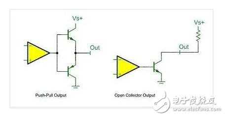
The push-pull output and the open-drain output are summarized by a simplest graph: the left side of the figure is the push-pull output mode, in which the lower PNP transistor is turned off when the comparator outputs a high level, and the upper NPN transistor is turned off. On, the output level is VS+; when the comparator outputs a low level, the opposite is true, the PNP transistor is turned on, and the output is connected to the ground, which is low. The right side can be understood as an open-drain output form that needs to be pulled up.
Third, floating input: For floating input, I have not found a very authoritative explanation, I have to understand from the following figure

Since the floating input is generally used for external key input, combined with the input part circuit on the graph, I understand that the floating IO input state, the IO level state is uncertain, completely determined by the external input, if it is floating at this pin In the case of reading the level of the port is uncertain.
Fourth, pull-up input / pull-down input / analog input: These concepts are well understood, can be easily read from the literal.
V. Multiplex open-drain output, multiplexed push-pull output: can be understood as the configuration when the GPIO port is used as the second function (ie not used as a general-purpose IO port)
Sixth, summarize the selection of IO mode in STM32
1, floating input GPIO_IN_FLOATING - floating input, you can do KEY recognition, RX1
2, with pull-up input GPIO_IPU - IO internal pull-up resistor input
3, with pull-down input GPIO_IPD - IO internal pull-down resistor input
4, analog input GPIO_AIN - application ADC analog input, or low power consumption
5, open drain output GPIO_OUT_OD - IO output 0 is connected to GND, IO output 1, floating, requires an external pull-up resistor to achieve output high level. When the output is 1, the state of the IO port is pulled high by the pull-up resistor, but since it is the open-drain output mode, the IO port can be changed to a low level or unchanged by an external circuit. Can read IO input level changes to achieve C51 IO bidirectional function
6, push-pull output GPIO_OUT_PP - IO output 0 - GND, IO output 1 - VCC, read input value is unknown
7, push-pull output of the multiplex function GPIO_AF_PP - on-chip peripheral functions (I2C SCL, SDA)
8, open-drain output of the multiplex function GPIO_AF_OD - on-chip peripheral functions (TX1, MOSI, MISO.SCK.SS)
Seven, STM32 settings example:
1. Analog I2C uses open-drain output _OUT_OD, connected to pull-up resistor, can correctly output 0 and 1; GPIO_SetBits (GPIOB, GPIO_Pin_0) when reading value; pull high, then can read IO value; use GPIO_ReadInputDataBit(GPIOB, GPIO_Pin_0 );
2. If there is no pull-up resistor, IO defaults to high level; need to read the value of IO, you can use pull-up input _IPU and floating input _IN_FLOATING and open-drain output _OUT_OD;
Eight, there are usually five ways to use a pin function, they are configured as follows:
1. As an ordinary GPIO input: configure the pin as a floating input, with a weak pull-up input or a weak pull-down input as needed, and do not enable all the alternate function modules corresponding to the pin.
2. As an ordinary GPIO output: Configure this pin as a push-pull output or an open-drain output as needed, and do not enable all the alternate function modules corresponding to this pin.
3. As a normal analog input: configure this pin to be in analog input mode, and do not enable all the alternate function modules corresponding to this pin.
4. As the input of the built-in peripheral: configure the pin as a floating input, with a weak pull-up input or a weak pull-down input as needed, and enable a certain multiplexing function module corresponding to the pin.
5. As the output of the built-in peripheral: Configure this pin as the multiplexed push-pull output or multiplex open-drain output as needed, and enable all the multiplexed function modules corresponding to this pin.
Note that if there are multiple multiplexed function blocks corresponding to the same pin, only one of them can be enabled, and other modules remain inactive. For example, to use the 47, 48-pin USART3 function of the STM32F103VBT6, you need to configure the 47-pin as the multiplexed push-pull output or the multiplexed open-drain output. Configure the 48-pin as an input mode, and enable the USART3 and keep the I2C2. Can state. If you want to use the 47 pin of STM32F103VBT6 as TIM2_CH3, you need to remap TIM2, and then configure the corresponding pin according to the multiplexing function.
Ebd Series Bench Lathe,Elf Night Vision Disposable Vape,Ksb Etachrom Bc Disposable Vape,Biglots Com Elf Disposable Vape
Longhua Manxueling Trading Company , https://www.mxlvape.com