With the continuous increase of labor costs, using robots instead of manpower to do some repetitive high-intensity labor is an important direction of modern robot research. The handling robot needs to coordinate the work of the rear wheel drive motor and the front wheel steering gear in the navigation tracing. The motor drive of the handling robot has its special application requirements. It has high requirements on the dynamic performance of the motor. It can reach the specified position required for control at any time and stop the steering gear at any angle. The torque range of the motor drive is large. The high-speed, low-torque working environment of the no-load flat road surface also has the operating conditions of full load climbing, and also requires high operating efficiency. According to the above technical requirements, this paper selects the DC motor with mature control technology and easy to smooth speed regulation as the implementation of the handling robot.
The power-driven design of the motor's power supply is provided by a 24V battery with a rated power of 240W, which is implemented by four 75N75 bridge circuits. The 75N75 is a MOSFET power tube with a maximum withstand voltage of 75V and a maximum current resistance of 75A. The motor drive circuit is shown in Figure 2. 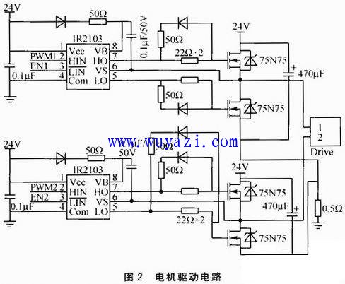
Q1, Q4, Q2, and Q3 form two bridges, respectively, which control the forward and reverse rotation of the motor. When the high-side driving MOS transistor is turned on, the source voltage and the drain voltage are the same and are equal to the power supply VCC. Therefore, to achieve normal driving of the MOS transistor, the gate voltage is larger than VCC, which requires a special boosting chip IR2103. The PWM signal generated by the controller is input to the HIN pin, and EN1 and EN2 of the controller I/O port output are used as enable signals. The output terminal HO can obtain a higher voltage than VCC, and the higher voltage value is exactly the voltage charged across the capacitor. The diode increases the conduction speed, making the on-resistance of the 75N75 smaller and reducing the loss of the switching tube. At the same time, the two output ports HO and LO of the IR2103 have an interlock function to prevent short circuit caused by the straight-through of the upper and lower arms of the motor due to software or hardware errors.
The design of overcurrent protection has two meanings in the installation of overcurrent protection in the motor control system. First, it prevents the motor from being overloaded or blocked during normal operation of the motor, causing the armature winding current to be too large to damage the motor or even cause a fire. On the one hand, the starting current is large when the motor is shoulder-moving, and often cannot be directly started. It is necessary to wait for the excitation winding to gradually establish a magnetic field and then operate normally, and it is desirable that the motor be shoulder-moved as fast as possible. With overcurrent protection, the current is chopped, allowing the motor to start safely and quickly. The schematic of the overcurrent protection is shown in Figure 3. 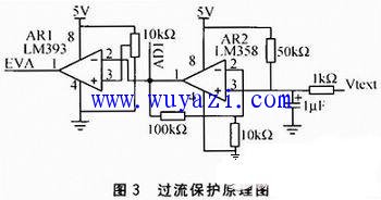
The phase current of the motor is converted into a voltage signal Vtext by the constantan wire, and the analog quantity AD1 amplified by the operational amplifier is sent to the controller A/D conversion module, and the digital quantity EVA after comparison by the voltage comparator is sent to the controller. External interrupt port. For the control requirements of the front wheel steering servo and rear wheel drive motor of the handling robot, the STM32F107 with Cortex-M3 core is used as the main controller, and the program is divided into the starting task and the motor by using the embedded real-time operating system μC/OS-II. The speed control task, the servo control task and other relatively independent multiple tasks, and set the priority of each task. The system can better realize the motion control of the handling robot.
Lcd Digital Signage,Digital Display Screen For Advertising,Signage Advertising,Menu Signage
Guangdong Elieken Electronic Technology Co.,Ltd. , https://www.elieken.com