Hello everyone, it's time to study everyday. Today we come to talk about jitter in digital circuit design.
Since it comes to jitter, what is jitter? First of all, let's find out what jitter is.
With the clock rate in the communication system stepping into the GHz class, jitter has gained increasing attention in the digital design field. In high-speed systems, timing errors in clock or oscillator waveforms limit the maximum rate of a digital I/O interface. Not only that, it can also increase the bit error rate of the communication link and even limit the dynamic range of the A/D converter. With this trend, designers of high-speed digital devices are also starting to pay more attention to timing factors. Jitter reflects the difference between two clock cycles. This error is generated internally in the clock generator and is related to the crystal or PLL internal circuitry. In addition, there is a kind of jitter caused by the change of the duty cycle of the signal in the cycle, which is called half-cycle jitter. In general, jitter can be considered as the sum of some accidental and indefinite changes in the clock signal itself during transmission.
************************************************** ************************************************** ********************
A few important concepts of jitter
The basic concept of jitter
In an ideal situation, the duration of a perfectly fixed pulse signal (for example, 1MHz) should be exactly 1us, with one edge every 500ns. Unfortunately, this signal does not exist. In fact, the length of the signal cycle will always have a certain change, leading to uncertainty about the arrival time of the next edge. This uncertainty is jitter.
Jitter is a measure of the time domain change of a signal. It essentially describes how much the signal period deviates from its ideal value. In most of the literature and specifications, the jitter is defined as the deviation of the arrival time of the high-speed serial signal from the ideal time. The difference is that in some specifications, the slowly changing component of the deviation is called time. Wander, and define the faster changing component as time jitter (jitter Wander reflects mainly the slow changes of the clock source over time, temperature, etc., affecting the absolute accuracy of the clock or timing signal. In signal transmission, both the sender and the receiver both use a certain clock architecture to allocate and synchronize the clock. Slow clock drift can be easily tracked or compensated. Therefore, wander has little effect on the bit error rate of digital circuit transmission. The main concern in circuit measurement is high-frequency jitter.
2. Classification of jitter
There are two main types of jitter: deterministic jitter and random jitter.
Deterministic jitter is caused by identifiable interfering signals, which typically have limited amplitude, have specific (rather than random) production causes, and cannot be statistically analyzed. Random jitter refers to timing changes caused by less predictable factors. For example, temperature factors that can affect the mobility of a semiconductor crystal material can cause random variations in carrier flow. In addition, changes in semiconductor processing, such as uneven doping density, can also cause jitter.
3. Jitter test method
Because the time deviation of the signal edge may be due to various factors, there is random noise, as well as deterministic interference. So the time bias is usually random, but there is a certain statistical distribution. In different applications, the result of this measurement may be measured by rms, or it may be measured by peak-peak. Complex occasions also decompose and estimate the components of this time offset. Therefore accurate measurement of jitter requires a large number of samples and complex algorithms.
************************************************** ************************************************** ********************
Second, the measurement method of jitter
The characteristics of jitter can be determined by many basic measurement indicators. The basic jitter parameters include:
1. Period jitter
Measure the width of each clock and data cycle in the real-time waveform. This is the earliest and most direct way to measure jitter. This indicator shows the change of the clock signal every cycle.
As the result of the periodic jitter measurement of a 50 MHz clock signal with jitter, the corresponding signal jitter analysis software observes the curve of the signal period as a function of time, as well as the maximum, minimum, and peak-to-peak values ​​of the signal period. The variance of the cycle, etc. 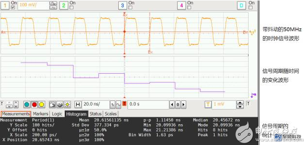
2. Cycle to Cycle jitter
In order to measure the speed of the clock signal's adjacent cycles, it is sometimes measured by “period-to-period jitter†to measure how much the cycle width of any two adjacent clocks or data changes, and by applying first-order differential operations to the periodic jitter, Can get jitter during the week. This indicator has a significant significance when analyzing the nature of the phase-phase loop.
Some special applications (such as clock signals for DDR2/3) also define N-cycle jitter, which is the jitter variation of adjacent N clock cycles. The following figure shows the results of the Cyclic-Cycle jitter measurement and statistics for the same 50MHz clock waveform. 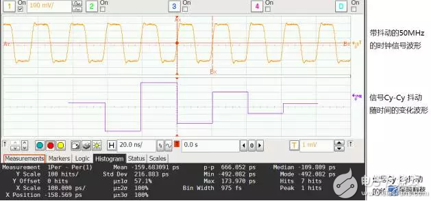
3. Time Interval Error
The so-called time interval error refers to the jitter of the edge of the measured signal relative to its reference clock.
Measure how far each active edge of the clock or data deviates from its ideal position. It uses the reference clock or clock recovery to provide the ideal edge. TIE is particularly important in communication systems because he explains the cumulative effect of periodic jitter over various periods.
The following figure shows the analysis and statistical results of TIE jitter for the same 50MHz clock signal. 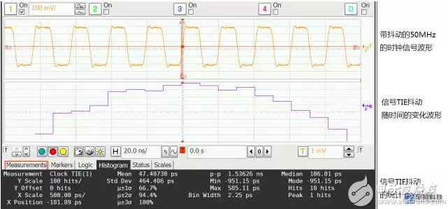
************************************************** ************************************************** ********************
III. Conclusions From the previous examples, we can see that for the same signal, measuring and measuring in different ways, the results obtained may be different. As shown in the figure, for the same jittered clock signal, the periodic jitter measurement, cycle-to-period jitter measurement, and time interval error jitter measurement are performed, and the results obtained may be different.
Therefore, before a jitter measurement is performed on a signal, it is necessary to clearly identify the type of jitter. Otherwise, the physical meaning of the measurement result is unclear. 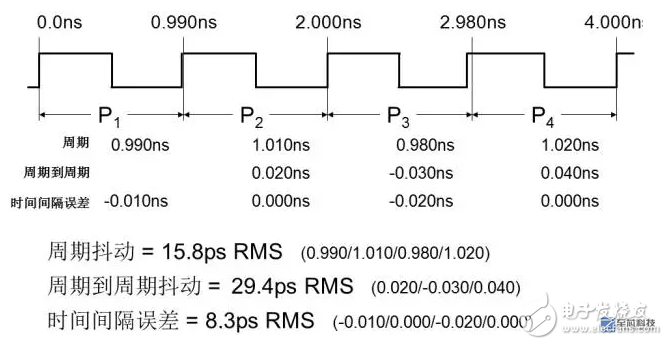
For more complex digital signals, in addition to the jitter RMS value and peak-to-peak value, the different components of the jitter are also concerned, because the jitter of different components is not the same for the circuit, and the corresponding countermeasures are also Different. For example, many high-speed buses will further decompose and study Random Jitter, Periodic Jitter, and Inter-Symbol Interference Jitter of high-speed digital signals.
Jitter is a very important concept of digital signals, especially high-speed digital signals. The faster the signal is, the shorter the bit period is, and the more stringent the requirement for jitter is.
Talk to you today, everyone, come on!
​Cable Tie
Cable Tie,Double Loop Cable Tie,Waterproof Cable Tie,1-Piece Edge Clip Cable Tie
Wenzhou Langrun Electric Co.,Ltd , https://www.langrunele.com