Abstract: The three-dimensional model of tilted image of UAV is fast and low cost, and it becomes the first choice for three-dimensional modeling of the city. In the three-dimensional modeling of tilt image of drones, data redundancy, model deformation, and missing images often affect the modeling results. In this paper, a series of corresponding model refinement processing technologies are proposed for the problems in the three-dimensional modeling of tilted images of UAVs, making the three-dimensional models more vivid and realistic.
Tilting images are image data collected from multiple angles at the same time. Using tilted images to create three-dimensional models not only greatly reduces the cost of expensive three-dimensional modeling, but also effectively improves the speed and efficiency of three-dimensional modeling.
At present, the three-dimensional model of the UAV tilt image construction provides comprehensive, accurate and detailed three-dimensional geographic information for the construction of smart cities and complex geo-hazard monitoring, and is widely used in many fields. However, in the practice of three-dimensional modeling of tilt image of UAV, there are many problems such as data redundancy, model deformation, and missing image in various technical links such as image preprocessing, aerial triangulation, and model establishment.
In response to these problems, the author proposes a series of corresponding technical measures to enable the three-dimensional modeling of the tilt image of the UAV to realize the refinement of the model.
1 Key technologies for 3D modeling of tilt camera images
The key technologies for 3D modeling of tilt camera images include data preprocessing, aerial triangulation, multi-view image intensive matching, and texture mapping [2].
Tilt image data preprocessing is mainly format conversion, rotation image, distortion correction and enhancement processing. The aerial triangulation is based on the coordinates of aerial image points measured on aerial photographs. It adopts a strict mathematical model and adopts the principle of least squares, adopts a small number of ground control points as adjustment conditions, and quickly solves the problem of image orientation and ground point encryption [ 3].
The empty triple solution of the oblique image is the process of converting the oblique image into an orthoimage, including the steps of image preprocessing, image joint adjustment, feature point-based image matching, and orthophoto image generation.
The commonly used image matching methods are based on square gray matching algorithms, such as correlation function method, covariance function method, correlation coefficient method, difference square sum method, difference absolute value method, least square image matching method, etc. The image matching method is based on the matching algorithm of image features, such as pyramid multi-level image matching algorithm, SIFT algorithm, etc. [4].
The SIFT algorithm has obvious advantages in the number of feature points extraction. It is to find a local feature vector set from an image according to the set threshold, which can well identify and match the local target. There is a large deformation such as rotation, Scaled, scaled image.
Texture mapping is the final step in the 3D modelling process and is the key to enhancing the visual effects of the model. In layman's terms, texture mapping is a two-dimensional to three-dimensional mapping relationship.
The process of mapping texture pixels in the texture space to pixels in the screen space is essentially the establishment of two mapping relationships from the screen space to the texture space and the texture space to the scene space [5].
Complex 3D models have complex surfaces and require multiple images from different viewpoints as texture maps to allow texture mapping for the entire model.
2 3D modeling problems and fine processing of 3D models
2.1 Image Preprocessing
2.1.1 Image distortion correction
Due to the characteristics of the center of the camera projection, the magnification of the image in different areas on the focal plane is different, which causes the deformation of the center of the photo to the edge of the photo in order. Under normal circumstances, slight distortion has little effect on the quality of the picture, but if the distortion of the building is too serious, it will distort the geometric characteristics of the picture, and the picture needs to be corrected for distortion. Image distortion correction method is to open the MapMatrix software-tool-digital camera image correction, and then open the distortion tool-add image-fill correction parameters-correction. Calibration interface shown in Figure 1
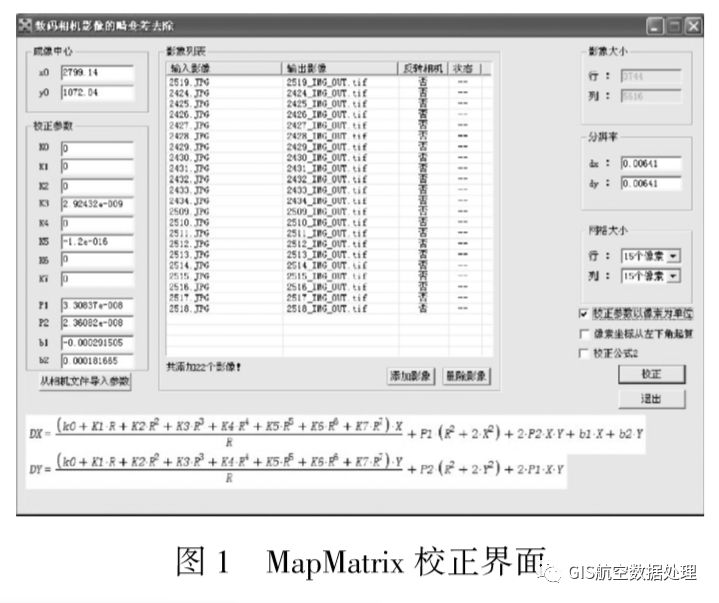
Parameter settings include: coordinates and unit definition, resolution, imaging center, calibration parameters, added images, grid size, distortion removal. After the above parameters are set and checked, click the "correction" button to remove the distortion. After the completion, the corrected TIF and TFW files can be generated in the output folder.
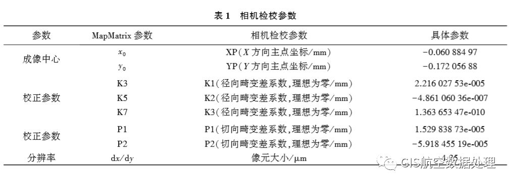
(1) Fill in the calibration parameters with the camera as shown in Table 1.
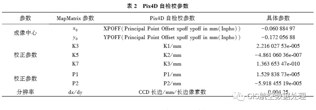
(2) Fill in Table 2 with Pix4D self-check parameters.
2.1.2 Data Redundancy and Data Filtering Scheme
Because tilt image modeling needs to acquire side texture information, and the actual physical conditions are complex, the aerial camera overlap design is high, and the amount of image data collected is huge, and there is a lot of data redundancy [6]. In order to efficiently and quickly model the images must be screened.
The specific method of data filtering is as follows: first edit the POS data acquired in the study area (POS data editor), then save and generate the KML file, and then import the KML file into Google Earth to edit the attributes, change the icon, and color (as shown in Figure 2). Show), and set the route and image to "stick to the ground" (as shown in Figure 3) for selection.
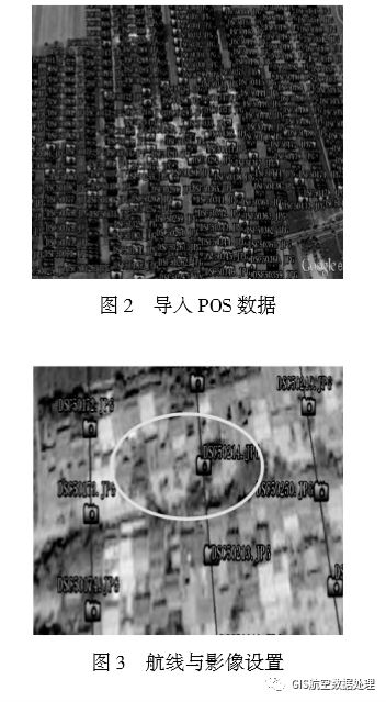
The selection principle is mainly to set the route and image height to “stick to the groundâ€, determine which images are above the area according to the required area, and then select the image closest to it. As shown in FIG. 3, the ellipse area can be selected under the premise of ensuring the overlap degree. DSC50214.jpg, DSC50173.jpg, DSC50215.jpg, DSC50213.jpg, and DSC50250.jpg are five images.
2.2 Aerial Triangulation
2.2.1 Model Deformation and Model Refinement
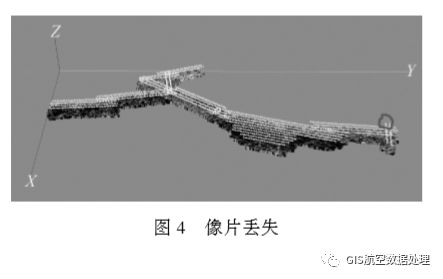
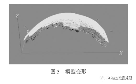
The lack of aerial triangulation photo is due to the quality of the image and POS parameters, and errors occur in the matching, resulting in voids or deformation of the model at the later stage of modeling. The missing picture is shown in Fig. 4. The circled picture is the missing picture. The model deformation is shown in Fig. 5.
There are two methods for dealing with model refinement that occur during aerial triangulation. The first method is:
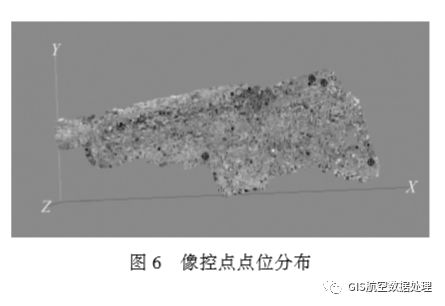
(1) The image control point is punctured in the corresponding image, and the same object is present on at least three images. The target image of the image control point should be clear, and it is easy to judge the puncture and stereoscopic measurement. The control point is shown in Figure 6.
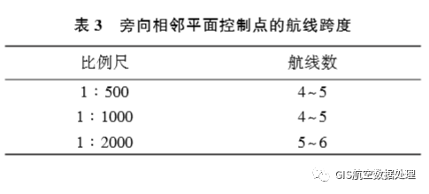
(2) The regional network deployment scheme is: When using two or more parallel routes with regional network deployment points, the requirements are as follows: a. The number of baselines between the control planes of adjacent planes can be estimated by referring to formula (1) [7]

In the formula, ms is the error in the plane of the connection point (empty three-encryption point) in units of millimeters; K is the multiple of the photograph enlarged and graphed; mq is the error in unit weight of the disparity measurement, and the unit is mm); n is the number of interval baselines for the adjacent plane control points in the flight direction. b. See Table 3 for the span of the adjacent horizontal plane control point.
c. The number of baselines for heading adjacent elevation control points can be estimated by referring to formula (2) [8]

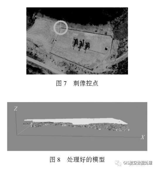
In the formula, mh is the elevation error of the connection point (empty triple encryption point) in meters (m); H is the relative altitude, in meters (m)); b is the length of the baseline of the image in millimeters ( Mm)); n is the number of interval baselines of the adjacent plane control points in the flight direction. By piercing the control point of the aerial patch, it is ensured that one control point appears on at least three photos, and the stab control point is shown in FIG. 7 . Then perform aerial triangulation to calculate the position and posture parameters of the photos, and retrieve the missing aerial photos. For the missing aerial photos, choose to continue to find the aerial photos or delete the aerial photos by piercing the control points to complete aerial triangulation aerial photos. The processing of missing and model deformation problems is shown in Figure 8.
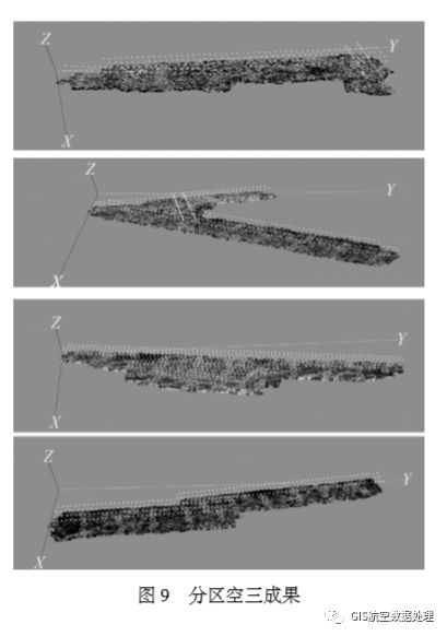
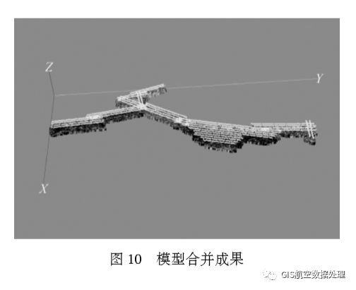
The second method is as follows: For the band survey area, triangulation can be performed by using partition modeling method, and then the three-dimensional reconstruction is performed. Finally, the model of each area is edged by using the common point of the adjacent area to prevent deformation of the model. Figure 9 shows the results of subarea modeling, and Figure 10 shows the results of partition modeling and synthesis.
2.2.2 Comparison of Different Modeling Methods
Method 1: The distorted photo plus raw POS data (latitude and longitude data + HPR corner element system).
Method 2: Undistorted photo plus original POS data (latitude and longitude data + HPR angle element system) plus distortion parameters.
Method 3: The distorted picture plus picture outer orientation element (XYZ+DPK corner element system) is used, and then the empty three encryption is performed in the Smart 3D, and the empty three-setting step is performed, and “adjust†is selected.
Method 4: The distorted picture has been added to the outer-picture element of the picture, and then the empty three-encryption is performed in the Smart 3D, and the empty set of three steps is selected, and “compute†is selected.
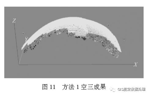
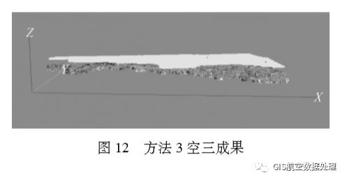
Experiment 1: Using the data from the same survey area, we used methods 1, 3, and 4 to perform aerial triangulation in the Smart 3D software. Method 1 is the longest, 5.5 hours, and the empty three encryption results are distorted, and 4 pictures are lost, as shown in Figure 11. Method 3 uses 1h, the empty three-encryption result has no distortion, and the image loses 2 pieces, as shown in Figure 12. The method 4 used 2.5 hours, the empty three encryption results were not deformed, and 11 images were lost. By comparing the three methods, method 3 works best. Therefore, under the premise of having external orientation elements, method 3 can be used to perform three-dimensional modeling.
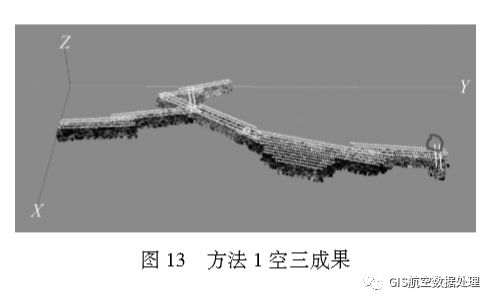
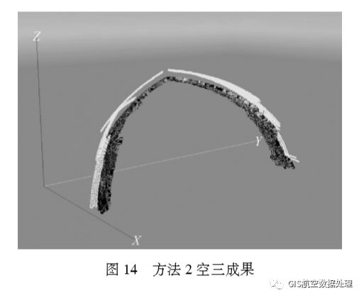
Experiment 2: Using the data from the same survey area, methods 1 and 2 were used to perform aerial triangulation in Smart 3D software. Using Method 1 to perform the empty three process took 6.5 hours, 15 images were lost, and the missing images were all at the corner of the route, as indicated by the circle in Figure 13. Because the distortion of the photo at the corner is relatively large, the photo at the corner should be deleted and then triangulated in the air. Using Method 2 to perform the airspace process took 8.5 hours, 19 images were lost, and the model was severely deformed, as shown in Figure 14. By comparison, Method 1 works well, so when performing three-dimensional modeling, you can first perform distortion correction on the photo.
Using Smart 3D for 3D modeling, various data sources mainly include cameras (single lens, five shots), photos (distorted photos, undistorted photos), POS data (longitude and latitude + HPR corner element system, differential POS, external orientation elements obtained through empty encryption, and image control points (GoogleEarth, RTK).
Through the comparison of Experiment 1 and Experiment 2, the data obtained by the five-lens camera + the distortion-corrected image + the external orientation element obtained by the air-free three-encryption + the image control point method using the RTK are obtained. The highest accuracy and the shortest time.
2.3 Model Deformation and Texture Deletion Model Refinement
2.3.1 Model Deformation and Texture Loss
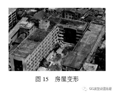
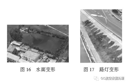
Insufficient data acquisition of dead data or data points where the oblique image is acquired will result in distortion of the model when it is model-matched, mainly in the foot of a building or feature [9]. The structural deformation of the house is shown in Figure 15. There is no or little texture on the surface of water, glass, etc., and there are no holes that match the feature points, as shown in Figure 16. Flagpoles, towers, street lamps, and billboards less than a certain thickness, because the matching cross-section is too small, can not produce enough feature points, resulting in missing models, street lamp deformation shown in Figure 17.
2.3.2 Fine Model Processing
Using DPModeler software, high-resolution aerial images are used for fluoroscopic imaging to quickly extract building outlines and automatically map textures to complete modeling [10–11]. Among them, multi-angle observing modeling of slanted images, the model and the image are completely fitted. The model has accurate three-dimensional coordinate information, and the model texture is automatically captured from the image, and one-click modeling is completed [12]. By creating a multi-level pyramid image structure and supporting seamless scheduling of images exceeding 100 million pixels, true shot images can be automatically generated, the projection difference of buildings can be corrected, and the problem of obscured shadows can be eliminated, and a model for Smart 3D automatic modeling can be realized. Deformation fine processing.
(1) The Smart 3D output data format is OSGB format. DPModeler cannot directly read the OSGB format data. Therefore, the osgConv software must convert the OSGB format data to the OSGB format that DPModeler can recognize.
(2) Import data into DPModeler for model refinement. For areas where the model is not fine or deformed, select the scope of the model to be modified through the "Plane Selection" tool, then rebuild the model through the reconstruction tool, set the inbound value, and complete the ground stitching.
(3) In the three-dimensional view, the deleted Mesh is displayed. According to the displayed Mesh in the three-dimensional free view, the reconstruction of the model is completed by making a model and an automatic texture mapping step, as shown in FIG. 18 .
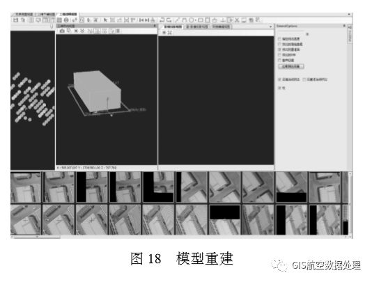
In FIG. 18, the leftmost side is a camera layout view, where different grayscale points respectively represent a vertical image, a tilt image within the range, and a computer-preferred image.
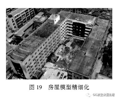
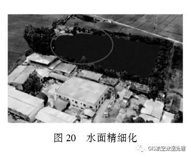
(4) In the texture automatic mapping step, if the texture is not clear or incomplete, the image can be directly imported into the PS for processing. After processing, the DPModeler is then imported for texture mapping. The result of the house refinement processing is shown in FIG. 19, and the result of the water surface refinement processing is shown in FIG. 20.
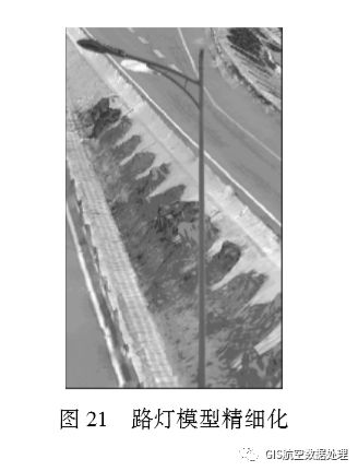
(5) For iron towers, street lamps, flagpoles, billboards less than a certain thickness, the processing method is to export the data in OBJ format in Smart 3D, and then import 3dsMax to refine the model, complete the model and texture mapping steps, and finally Then import Smart 3D. The street light refinement processing result is shown in FIG. 21 .
2.4 How to deal with missing texture information on the side of the model
If the survey area is surrounded by mountains, it will cause a large height difference in the survey area. It is difficult for the drone to shoot images, so it can only be shot with a single-lens camera. Because the image data is taken from the sky, the model lacks side texture information, resulting in incomplete model of the low ground. In order to make up for this deficiency, it is possible to use ground-based imagery in combination with top-view photography to obtain images.
There are two ways to deal with the lack of texture information on the side of the model:
(1) Three-dimensional modeling using images captured on the ground, and then replacing modeling results from single-lens top-down shooting, and performing space integration.
(2) At low altitude, drone image acquisition is performed in areas where the model is poor, and orthophoto image acquisition is performed for the vegetation coverage area. Due to the large height difference, low-altitude oblique image acquisition can be performed on the areas with houses. The texture is complete.
3 Conclusion
Utilizing the tilt image of UAV to make 3D model is a widely used 3D modeling method. This paper analyzes the problems often encountered in the 3D modeling practice of UAV tilt image and proposes a series of 3D model refinement. The processing method is expected to have certain reference and reference value for the practice of 3D modeling of tilt image of UAV.
Power X (Qingdao) Energy Technology Co., Ltd. , https://www.solarpowerxx.com