If you compare cars to people, then VCU is the human brain. Here, the status of the vehicle chassis (vehicle speed, accelerator pedal opening, brake pedal status, steering wheel angle, etc.), the status of the vehicle body (door state, window state, headlight status, turn signal status, etc.) and the engine's State (speed, output torque, fuel consumption, etc.). As sensors inherent in automobiles, using these signals not only provides excellent control of the car, but also enables interaction with the outside world through the on-board signal lights. This article introduced the signal of the car VCU.
Foreword
This article will introduce the sensor signal that the car was born with, namely the signal obtained from the vehicle control unit (VCU).
VCU's other name is "Drive Computer". It communicates with various electronic devices such as the car's engine, transmission, accelerator pedal, brake pedal, and body controller through the CAN bus, and reads the operating status of each control unit. Control them when needed. As shown below.
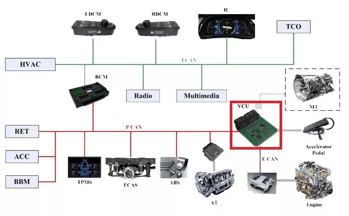
Image source: http://
If you compare cars to people, then VCU is the human brain. Here, the status of the vehicle chassis (vehicle speed, accelerator pedal opening, brake pedal status, steering wheel angle, etc.), the status of the vehicle body (door state, window state, headlight status, turn signal status, etc.) and the engine's State (speed, output torque, fuel consumption, etc.).
text
As the interface between the upper layer algorithm and the chassis control, the vehicle's VCU not only undertakes the tasks of controlling acceleration, deceleration, and steering of the car, but also bears the task of accurately transferring the chassis information to the algorithm layer in a timely manner. Next I will explain both the type of VCU signal and the application of the VCU signal.
Type of VCU signal
The VCU information (ChassisDetail) provided in Baidu Apollo 2.5 is as follows:
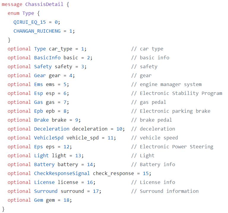
Picture source:
https://github.com/ApolloAuto/apollo/blob/master/modules/canbus/proto/chassis_detail.proto
Car Type
From the figure it can be directly seen that the current Apollo 2.5 has been able to support two domestic models are Chery EQ and Changan Rui Rui.
Because the power system, size, and function configuration of different models are all different, and the positions and angles of various sensors are also different, it is necessary to introduce different parameters into the unmanned system according to this Type value. Accuracy of calculations.
Basic Signal BasicInfo
The basic signal contains information on the current vehicle driving status, engine status, airbag status, mileage, ACC button status, LKA button status, and GPS information.
Personally, the most important information in BasicInfo is the vehicle driving status and GPS information. The driving state of the vehicle is a sign of whether the vehicle is in an unmanned state. Since cars often need to be switched between manned and unmanned, it is necessary to set a flag to reflect this state, so that the car's VCU can be more Correctly control the throttle and brakes that affect safety. The GPS information is strongly related to the "positioning" problem of the unmanned vehicle. Although the GPS information of the vehicle is not always accurate, it cannot shake its position in the unmanned system.
Safety Related Safety
Safety-related data includes doors and hoods, whether the trunk is closed, whether the driver's and passenger's seat belts are attached, whether the tire pressures of the four tires are normal, whether the batteries have electricity, and the driving mode of the vehicle.
It is worth mentioning that the driving mode of the vehicle. In the previous BasicInfo, there was already a vehicle driving state, which was divided into automatic driving and man-made driving. The driving mode here also has an intermediate state, ie semi-autonomous driving mode, ie the unmanned system only controls the steering wheel or only the throttle and brake pedal. Such as adaptive cruise (ACC) function, is a semi-automatic driving mode. The semi-autonomous driving mode can decouple the lateral control (turning, lane changing) and longitudinal control (acceleration, deceleration) of the vehicle, ie, one-dimensional debugging is performed separately, which can improve the debugging efficiency of the engineer.
Gearbox status Gear
Transmission status directly affects the driving of the vehicle. For example, when the vehicle is parked, a message for setting the P position of the transmission needs to be provided; when the vehicle is parked, it is necessary to switch back and forth between the D range and the R range.
Engine Management System EMS
The EMS is used to view the current state of the engine, such as the engine speed.
Vehicle Electronic Stability System EPS
Used to view and control the status of the vehicle's electronic stability system.
Accelerator pedal opening GAS
By controlling the opening of the accelerator pedal, acceleration and deceleration can be achieved. At the same time, whether the tester takes over the accelerator pedal can be fed back without driver.
Electronic hand brake EPB
Used to check the status of the electronic handbrake. Generally, when controlling the movement of a vehicle, it is checked whether the electronic hand brake is released.
Brake pedal opening Brake
Used to view and control the opening of the brake pedal. Feedback The tester took over the brake pedal without driver.
Brake Pressure Deceleration
Used to check the current brake pressure.
Car Speed ​​VehicleSpd
In addition to the speed value, the vehicle speed signal also includes the current car's driving direction, the speed of the four tires, and the Yaw Rate (YawRate).
Electric power steering EPS
The electric power steering signal includes the current steering wheel angle, the rate of change of the corner, and the driver's applied torque. When in an unmanned state, the controller needs to input the rotation direction and rotation angle to the EPS system.
Signal Light
Describe signals of certain electrical devices on the car body, such as headlights, left and right turn signals, wiper gear switches, and horn switches. Tesla obtains the intention of the driver to change lanes by reading the state of the lever (left and right turn signals).
Battery Status Battery
Used to check the percentage of battery power, fuel volume information.
Surrounding status Surround
Some models with ADAS functions (such as blind spot assist warning and lane departure warning) will have some warning information stored in this signal. The ultrasonic radar installed on the car body also has this signal.
The above lists the signals that most car VCUs have. The VCU signal varies from car to car. The more luxurious the car, the richer the sensors it has, the more VCU signals it can provide.
Application of VCU signal
VCU signals commonly used in unmanned vehicles are as follows: vehicle speed, car steering wheel angle, vehicle heading angle change rate, accelerator pedal opening, and brake pedal opening.
Different scenarios have different ways of applying data. Here are two main types of applications: obstacle motion status calculation and dead reckoning.
Obstacle motion status calculation
The obstacle speeds detected by on-board sensors (laser radar, millimeter wave radar, and camera) are all relative speeds. Therefore, it is necessary to combine the speed of the vehicle to determine the absolute speed of the obstacle and then determine the motion state of the obstacle based on the absolute speed (stationary, approaching). ,keep away).
Taking millimeter-wave radar data as an example, the speed of the vehicle in the vehicle's own coordinate system is indicated by blue arrows and letters, and the position of the obstacle and the speed and speed of the obstacle in the x-direction and y-direction are indicated in green.
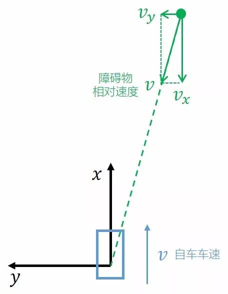
By superimposing the components of the vehicle speed v and obstacle speed in the x direction, the absolute value of the speed of the obstacle in the x direction can be obtained. The black Va is shown in the figure below.
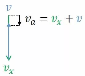
Then we can judge the size and direction of Va, and then get the current obstacle movement in the actual traffic scene.
Dead reckoning
Dead reckoning (referred to as DR) refers to the use of information from the vehicle sensor in the case of missing positioning, and presumes the relative relationship between the current position of the vehicle and the location of the previous moment.
When introducing dead reckoning, you first need to understand the kinematic model of the car. The kinematics model of a car is generally a four-wheel model, but for the sake of calculation, in many cases, the engineers will reduce the four-wheel model to a two-wheel model, namely a bicycle model.
Borrow a bike model drawn by CSDN blogger AdamShan, as shown below.
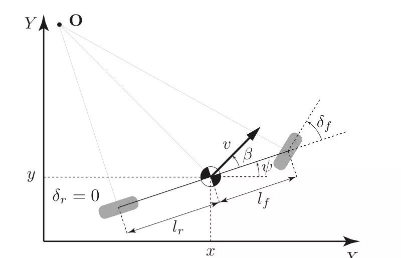
Image Source: https://blog.csdn.net/AdamShan/article/details/79083755
It can be seen from the figure that the wheel angle of the car is δf, but this does not mean that the car's movement angle is δf.
The rays that are perpendicular to the rear and front wheels are made separately. The two rays will cross at O ​​point. The two-wheel model will move around O point. Within a short time dt, it can be considered that point O does not move. Connect the point O and the center of mass of the car into a line segment. The direction of movement v of the actual car will be perpendicular to this line segment. The angle β between the direction of movement and the direction of the body is generally called the yaw angle.
Based on the previous assumptions, the approximate relationship between β and δf can be derived as follows:

Assume that the car's state at time t is xt, yt, and after t1 time at t+1, the state is xt+1, yt+1, and the relationship between them is:


According to the above theory, position and pose estimation can be performed by relying on its own sensor information within a short time after missing positioning information.
Of course more than two applications of the VCU signal, more applications will be introduced in the subsequent sensor signal processing.
Conclusion
The above content gives a brief introduction to the signal of the car VCU. As sensors inherent in automobiles, using these signals not only provides excellent control of the car, but also enables interaction with the outside world through the on-board signal lights.
The pin refers to the connection between the internal circuit of the integrated circuit (chip) and the peripheral circuit, and the pin constitutes the interface of the chip. According to the function, the pins of AT89S52 can be divided into four categories: main power supply, external crystal oscillator or oscillator, multi-function I/O port, and control, strobe and reset.
Terminal Pins,Terminal Hardware Pin,High Precision Terminal Pins,Terminal Pins For Pcb
Sichuan Xinlian electronic science and technology Company , https://www.sztmlch.com