PCI bus
PCI is the abbreviation of Peripheral Component Interconnect. It used to be the most widely used interface in personal computers. Almost all motherboard products have such slots. The bus is currently being replaced by the PCI Express bus.
PCI is the Peripheral Component Interconnect, which means "Peripheral Component Interconnect". It is a local parallel bus standard introduced by the PCI Special Interest Group (PCISIG). The PCI bus is developed from the Industy Standard Architecture (ISA) bus and is a synchronous, processor-independent 32-bit or 64-bit local bus. From a structural point of view, PCI is a bus that is inserted between the CPU provider and the original system bus. A bridge circuit is used to manage this layer, and an interface between the upper and lower interfaces is used to coordinate data transmission. . Since the creation of the specification in 1992, the PCI bus has become a standard bus for computers and is widely used in current high-end microcomputers, workstations, and portable microcomputers. Mainly used to connect display cards, network cards, sound cards.
Note: The ISA parallel bus has 8-bit and 16-bit modes. The clock frequency is 8MHz and the operating frequency is 33MHz/66MHz.
The PCI bus is a tree structure that is independent of the CPU bus and can operate in parallel with the CPU bus. PCI devices can be connected to PCI devices and PCI bridges. Only one PCI master device (at the same time) is allowed on the PCI bus. Others are PCI slave devices, and read and write operations can only be performed between master and slave devices. Data exchange between slave devices needs to transit through the master device.
Note: This does not mean that all read and write operations need to go through the Northbridge because the master and slave device properties on the PCI bus can change. For example, Ethernet and SCSI need to transmit data. This can be done through a method called Peer-to-Peer. In this case, Ethernet or SCSI is used as the master, and other devices are slaves. Specific details will be introduced in the post.

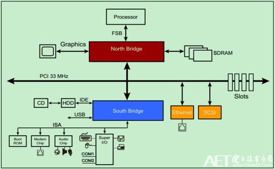
A typical 33MHz PCI bus system is shown in the figure above. The processor is connected to the Northbridge through the FSB. The northbridge is equipped with a graphics accelerator (graphics card), SDRAM (memory), and PCI bus. The PCI bus carries the Southbridge, Ethernet, SCSI bus (an old-fashioned minicomputer bus) and several PCI slots. CDs and hard disks are connected to South Bridge via IDE, audio equipment and printers, mice and keyboards are also connected to South Bridge, and South Bridge also provides a number of USB interfaces.
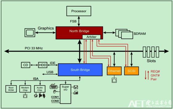
The PCI bus is a shared bus, so a special arbiter is needed to determine the current bus control. The arbiter is generally located in the North Bridge, and the arbiter (host) is connected to each slave through a pair of pins, REQ#(request) and GNT#(grant). As shown below:

It should be noted that not all devices are capable of being called an Arbiter or initiator.
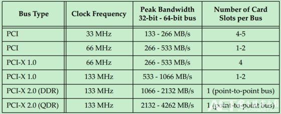
The initial PCI bus clock frequency was 33MHz, but with the newer version, the clock frequency gradually increased. However, because PCI uses a Reflected-Wave Signaling signal model (described later in detail), the higher the clock frequency, the smaller the maximum bus load, as shown in the following figure:

With the PCI-X 2.0 version, only one PCI card can be inserted in the entire bus (equivalent to two PCI loads). In order to provide more slots on the motherboard, it must be implemented by connecting multiple PCI bridges.
Right Angle DIP Centronic Connector
Right Angle DIP Centronic Connector.
Current Rating:5A
Dielectric Withstanding Voltage:1000V for one minute
Insulation Resistance:1000MΩ Min.(at 500V DC)
Contact Resistance:35mΩ Max.
Temperature:-55°C to +105°C
Right Angle DIP Centronic Connector
ShenZhen Antenk Electronics Co,Ltd , http://www.coincellholder.com